Ready to test your soldering skills?
Teardown 2024 begins today in Portland and Darcy has designed and kitted an exciting SMD soldering challenge!
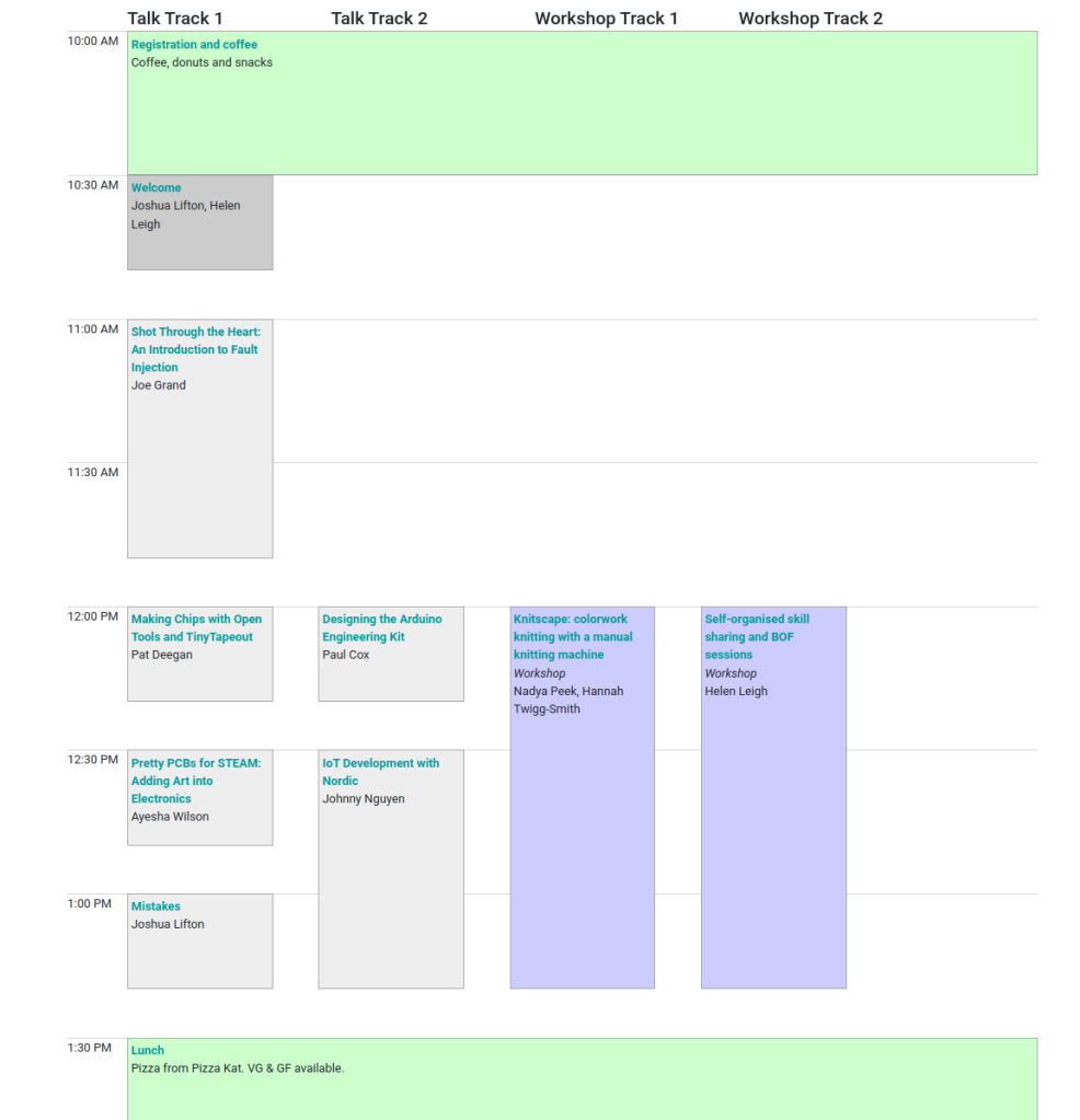
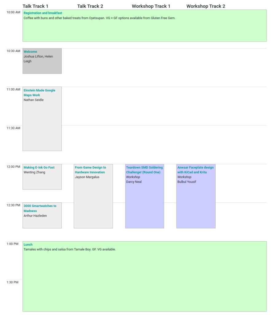
Teardown SMD Soldering Challenge! (Round One)
June 21, 2024 12:00-12:50 PM
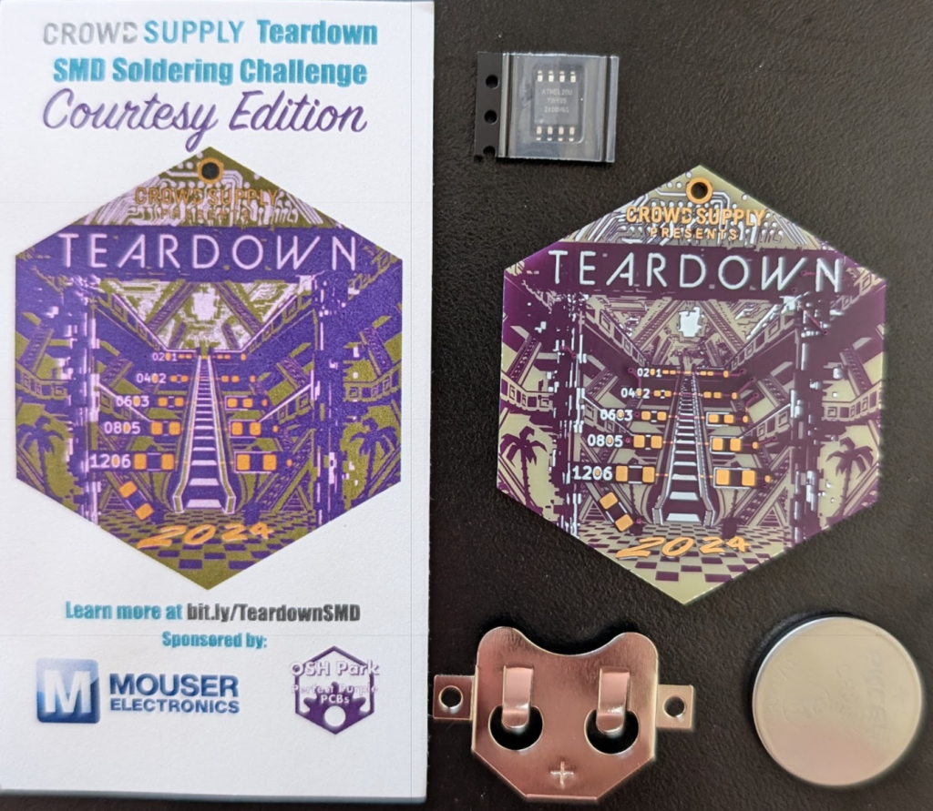
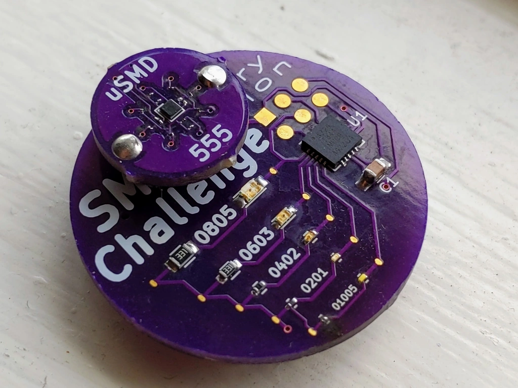
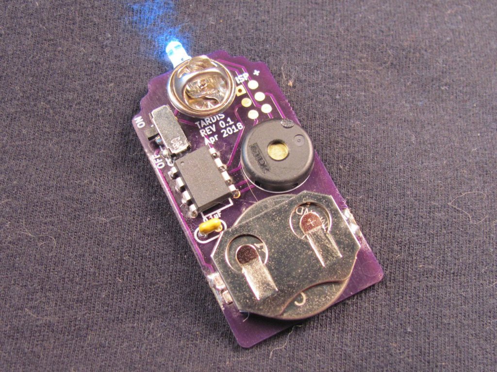
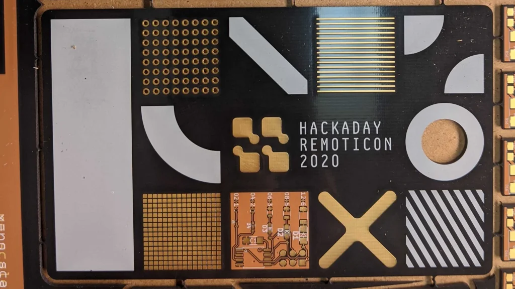
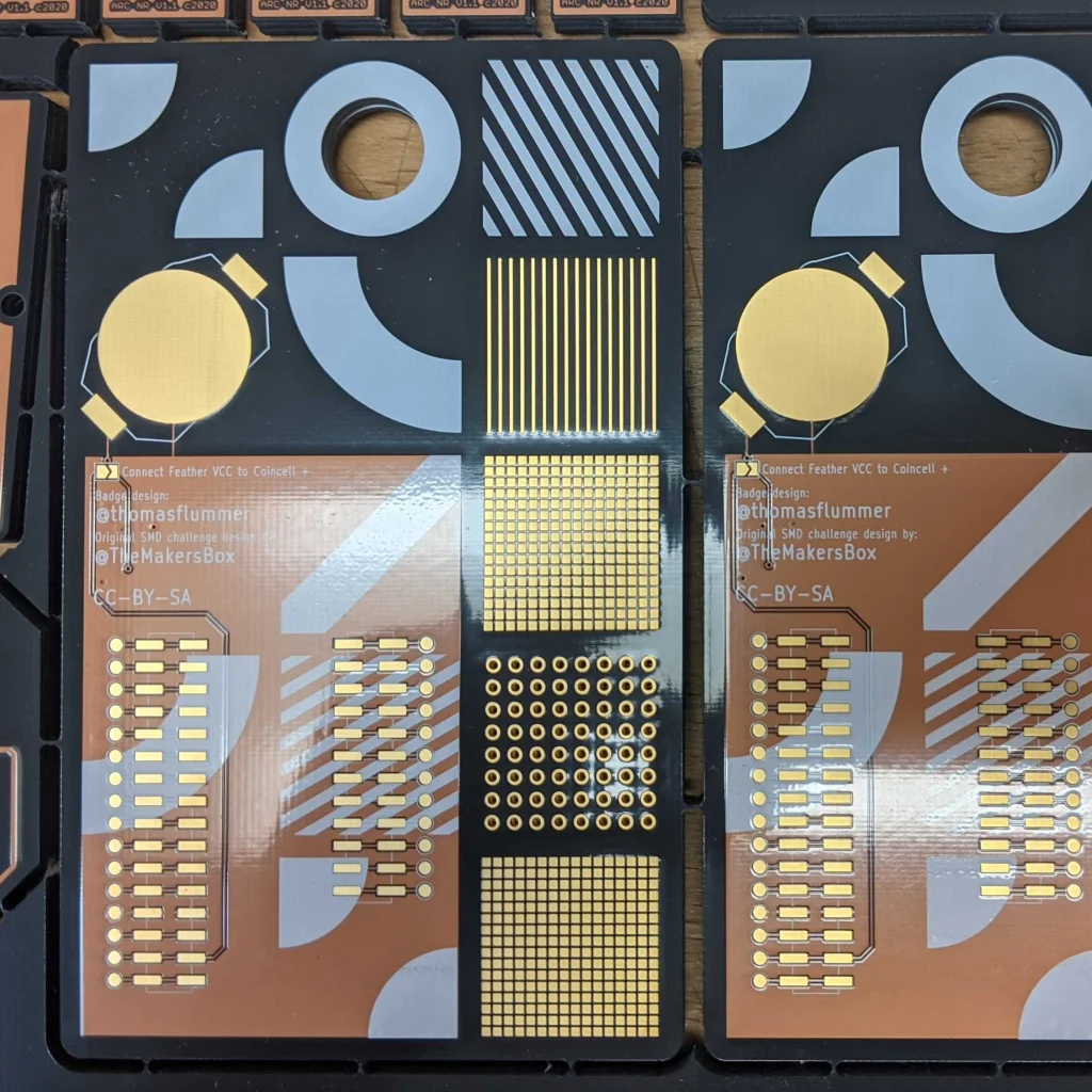
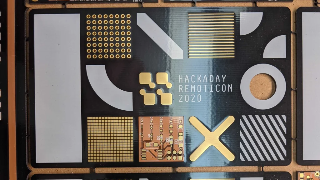
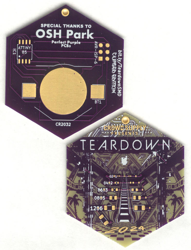
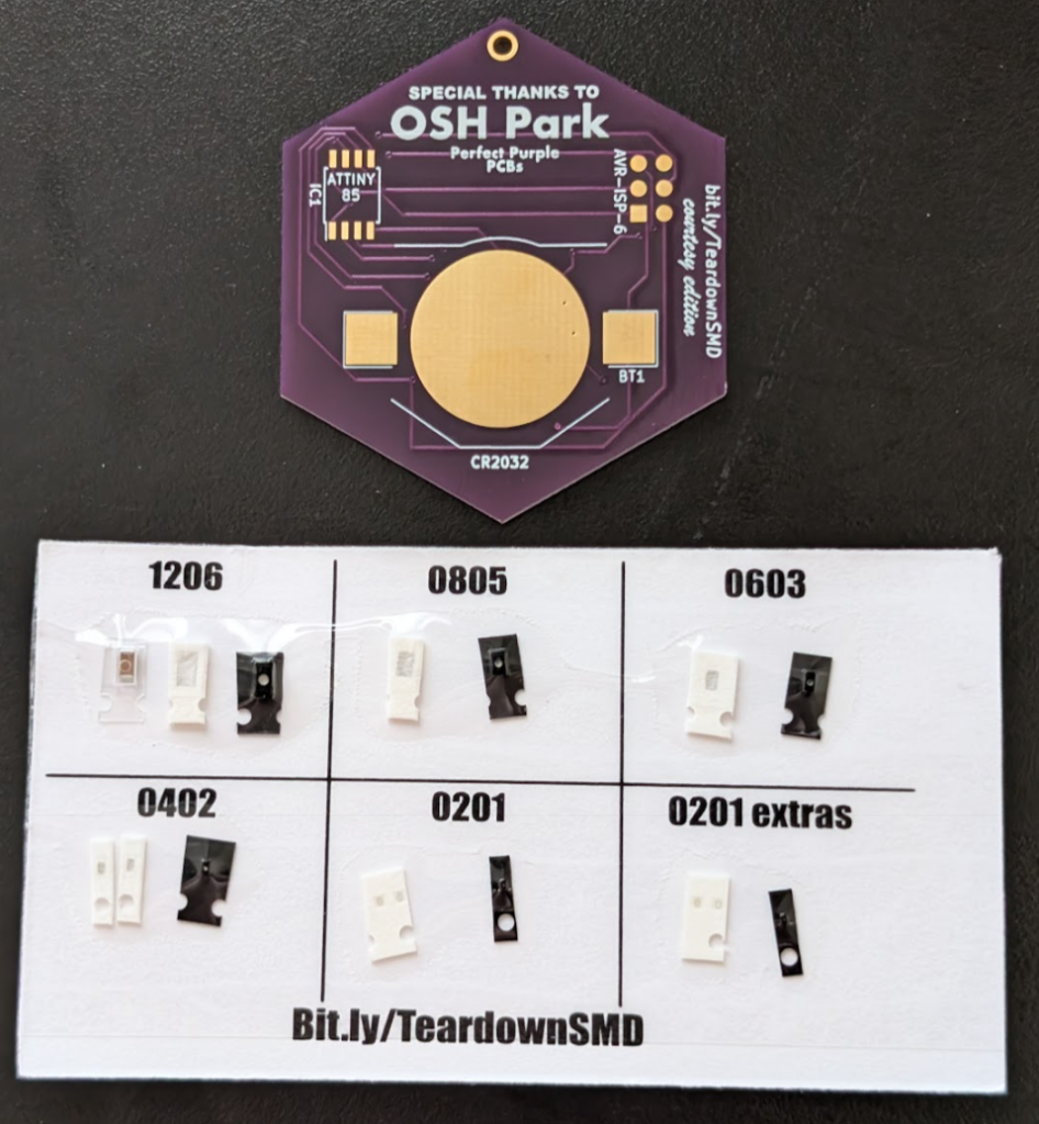
Put your surface mount soldering skills to the ultimate test! Begin with the manageable 1206 package and take on increasingly tiny components, each step pushing your abilities further. This SMD project is powered by a CR2032 coin cell and an Attiny85 SOIC, offering a perfect blend of challenge and excitement. Brace yourself for the ultimate trial: hand soldering a 0201 package, a feat so intricate it will have you questioning your sanity. Are you ready to show off your skills and conquer this soldering adventure?
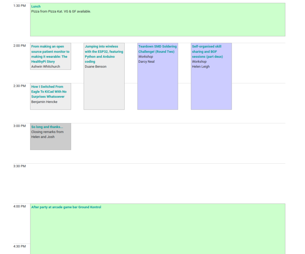
Teardown SMD Soldering Challenge! (Round Two)
June 23, 2024 2:00-2:50 PM
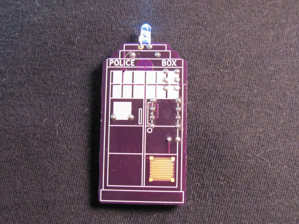
Put your surface mount soldering skills to the ultimate test with this gorgeous Teardown-themed SMD Challenge board! Begin with the manageable 1206 package and take on increasingly tiny components, each step pushing your abilities further. This SMD project is powered by a CR2032 coin cell and an Attiny85 SOIC, offering a perfect blend of challenge and excitement. Brace yourself for the ultimate trial: hand soldering a 0201 package, a feat so intricate it will have you questioning your sanity. Are you ready to show off your skills and conquer this soldering adventure?
This workshop is first come first serve, limited to 20.