Hackspace column on PCB design

My recent Hackspace magazine column is an introduction to printed circuit boards (PCBs) and how they can improve DIY projects:

PcB

PCB love – making circuit boards

You made your first LED blink, you learned how to use a breadboard, and you know which end of the soldering iron to hold. So what’s next? High up on the list of essential electronics skills is learning how to design and make your own printed circuit board (PCB). My first PCB was a POV (persistence of vision) display, a modified version of an Adafruit open hardware design. I still remember how exciting it felt to open up my mail and solder a board I designed myself!

A PCB is a board with traces (lines) that connect different pads or holes for electronic components to each other, or to connectors that allow us to hook up power, microcontrollers, or other parts. We use solder to connect the pads or holes on the bare board to the component that the board was designed for. Once the components are in place, the traces let us push power or data around our boards.

Screenshot from 2020-05-21 14-23-56

PCBs themselves are like a sandwich made up of layers of different materials. The main ‘body’ of a PCB is made of some kind of substrate; typically a fibreglass called FR4. On top of that is a thin layer of copper-foil that lays out the traces and pads, then a layer of coloured solder mask which prevents solder from sticking where it shouldn’t.

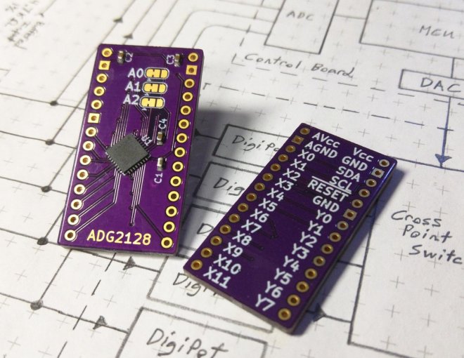
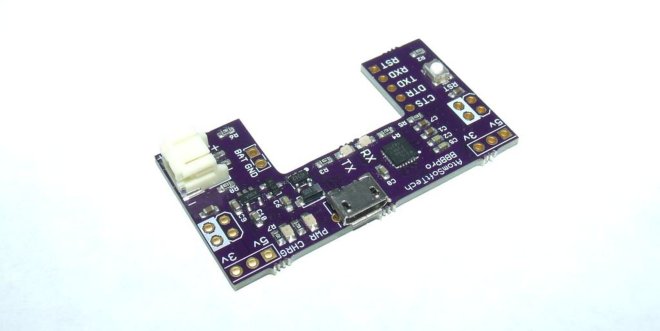
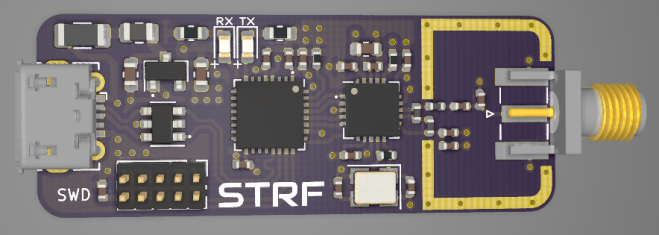
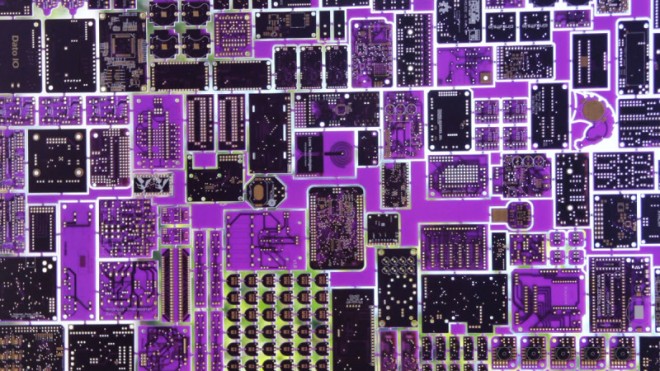
This solder mask is often green, but you can get all sorts of colours, such as my favourite – purple. The copper that is not covered by solder mask then gets protected by a surface finish such as HASL (solder) or ENIG (gold plating). Finally, there is the silkscreen layer where text and symbols are printed.

Like any good sandwich, you can keep adding in more layers of copper, from two layers up to tens of layers. It’s also worth knowing that rigid fibreglass isn’t your only option: you can choose a material called Kapon (polyimide film) to make flexible PCBs. You can even make your PCB sandwich using both fibreglass and Kapon to make a board that is flexible in some places and rigid in others. One super-cool option, that both OSH Park and Evil Mad Scientist Laboratories have been using recently, is black fibreglass paired with a clear solder mask, so all your copper traces are visible.

In next month’s column, I’ll be talking about the awesome ways the hardware hacker community has been using PCB design to make cool electronics projects and beautiful art, as well as sharing some of the tools they’re using to make their boards. In the meantime, I recommend this excellent video that visualises the composition of a PCB: hsmag.cc/SI2m31 (How do PCBs Work?  by Branch Education).

Hackspace column on PCB design

Breakout board for 8×12 analog cross-point switch

J. Ian Lindsay of  Manuvr Breakouts has designed this breakout board for Analog Devices’ 8×12 analog cross-point switch:

2019-12-01T08_58_25.068Z-IMG_20191201_013632

ADG2128 Breakout

The ADG2128 is an incredibly flexible cross-point switch. It supports 5/-5v, 3.4MHz i2c, and is unrestricted as to its connectivity options between its rows and columns.

This is a high-dollar part, and I’ve been designing with it for more than 5 years. So I polished my breakout board to reuse them during a project’s prototyping phase.

This board has decoupling capacitors adequate to handle the whole analog voltage range, i2c address selection jumpers, and differentiated ground layers for noise isolation or differential operation below 0v, according to the project’s demands.


Breakout board for 8×12 analog cross-point switch

Raybeacon 1.4 is out

The rayBeacon by Mike M. Volokhov is a Nordic nRF52 on-the-go development kit:

raybeacon-afterdark

Shared Project: Raybeacon 1.4

The Raybeacon is full-featured nRF52 based wearable, ultra-low power, multiprotocol development board designed for variety of embedded applications. Due to modular design, the device can be used to build your own production-ready appliance with minimal hardware modifications.

Key features include:

  • Coin sized – the board is only 25 mm in diameter
  • Works from a single CR2032 / CR2025 3V button cell
  • Nordic nRF52 high-end multiprotocol SoC supporting Bluetooth 5.x, Bluetooth mesh, Thread and Zigbee; of your choice:
    • nRF52833: Cortex-M4F 64MHz, 512KB flash, 128KB RAM, Bluetooth® 5.1 Direction Finding, 105°C temperature qualification
    • nRF52840: Cortex-M4F 64MHz, 1MB flash, 256KB RAM, Bluetooth® 5.0, ARM TrustZone® CryptoCell cryptographic unit
  • Automotive grade BOM components – ready for harsh environment
  • 2 x tactile buttons IP67
  • 1 x RGB LED
  • 1 x infrared LED (850 nm) 0402 size
  • Socket for NFC flex antenna, compatible with Nordic FPC antenna and Liard 0600-00061. Can be configured as extra 2xGPIO.
  • Programmable through SWD port (removable Tag-Connect socket, on-board solder pads)
  • 1.27mm pitch 2×4 receptacle to connect custom extension boards:
    • 6 x GPIO ports
    • 1 x 12-bit ADC input
    • pass-through VDD and GND pins
  • 2.54mm pitch 1×8 pin header for fast breadboard prototyping; can be reused as 1.27 to 2.54 adapter
  • USB interface (on-board solder pads)
  • Minimal fabrication cost due to simple, two-layers only design

For detailed description, including information on custom boards and source files, please refer to the project repository on Bitbucket. Also, feel free to share your thoughts, or submit a request for a new slice or report an issue!


Raybeacon 1.4 is out

BreadboardBuddy Pro

BreadboardBuddy Pro from AtomSoftTech on Tindie:

2015-01-25T14_12_11.357Z-Clipboard01

What is the Breadboard Buddy Pro

The BBBPro is a 4 in 1 breadboard tool. The amount of time you save using this is crazy! Ive been using my original Breadboard Buddy for years and the main addition is the newer CP2104 and Lipo Charging.

The board can be broken down into four main parts.

USB Power, USB 2 UART, LIPO Charger, Reset Button.

USB Power

Using a MicroUSB cable you can supply the board with its power. The board can output 5v and 3.3v simultaneously. Using the Jumpers on each of the top corners you can select which supply goes to which rail on breadboard.

If using a battery please note that there will obviously be no 5v supply. You can take 4.2 (or what ever the voltage on battery may be) from the BATT pin. Otherwise it will supply power to the 3.3v regulator and you can still use that on the power rails.

USB 2 UART

The USB to UART uses the CP2104, its a beautiful less expensive part than the FT232RL. It has a RX and TX led for indication of data transmission and reception. Supports 5/6/7/8 Data bits, Stop Bits 1/1.5/2, Parity odd/even/mark/space/none, Baud Rates 300bps to 2Mbits. Has a 576 transmit and receive buffer.

Lipo Charger

Uses the widely known and trusted MCP73831 for lipo charging. These ICs are so popular and tested so much that it almost guarantees your battery will be charged safely. The same charging circuit is used by other suppliers of similar circuits. What makes mines special is the ability to still supply power to circuit while charging, without crossing the voltage. Has a option for 100mA or 500mA charging on bottom. (Solder Jumper)

Reset Button

Just about any breadboard user knows how important a reset button can be. Using DIP MCUs are awesome for prototyping but all these extra components can take up so much space. This button isnt taking any space away. Also its pull up to 3.3v or 5v so you MCU is safe. (please ensure you select correct voltage on solder jumper on bottom) Can be used as a General Purpose pulled up button as well.

BreadboardBuddy Pro

KiCad 5.1.6 released

Screenshot from 2020-05-16 21-51-10

KiCad 5.1.6 has been released:

The KiCad project is proud to announce the latest series 5 stable release. The 5.1.6 stable version contains critical bug fixes and other minor improvements since the 5.1.5 release. It also includes improved footprint, symbol, and 3D model libraries, translations, and documentation.

This is also the first stable point release made since switching to gitlab for main kicad source code hosting.

A list of all of the fixed bugs since the 5.1.5 release can be found on the KiCad 5.1.6 milestone page. This release contains several critical bug fixes so please consider upgrading as soon as possible.

Read more…

KiCad 5.1.6 released

Flux Capacitor badge add-on

BTTF

We really like this “Back to the Future”-themed Flux Capacitor badge add-on (SAO) by Squaro Engineering made with our “After Dark” service (which features clear soldermask on black fiberglass substrate).

Checkout the GitHub repo for more: sqfmi/BTTF-BADGE

The board is also available an OSH Park shared project
Order from OSH Park

Flux Capacitor badge add-on

STM32L4-based RF-to-USB dongle

Philip Salmony has designed a STM32L4-based RF-to-USB dongle using a low-power NRF24 2.4GHz transceiver:

687474703a2f2f7068696c73616c2e636f2e756b2f77702d636f6e74656e742f75706c6f6164732f323032302f30352f535452462d33442e706e67

KiCad STM32 + RF + USB Hardware Design

Overview of STM32, RF, and USB hardware design, schematic creation, and PCB layout and routing in KiCad using a real-world example project. (Timestamps in description) Various tips on controlled impedance routing, differential pairs, USB, and RF layout. Correction in schematic: NRF24 IREF pin needs to be pulled low to GND via a 10k resistor (not to 3V3 as shown in the video!). Fix has been pushed to GitHub.

STM32L4-based RF-to-USB dongle

New Teensy 4.1 Arrives with 100 Mbps Ethernet, High-Speed USB, 8 MB Flash

It was only last August that PJRC released Teensy 4.0. At that time, the 4.0 became the fastest microcontroller development board on the planet, a title it still holds as of this writing — or, well, not exactly. Today the Teensy 4.1 has been released, and using the same 600 MHz ARM Cortex M7 under the hood, is now also the fastest microcontroller board. What the 4.1 brings to the table is more peripherals, memory, and GPIOs. While Teensy 4.0 used the same small form factor as the 3.2, Teensy 4.1 uses the larger board size of the 3.5/3.6 to expose the extra goodies.

The now slightly older Teensy 4.0 — released on August 7th of last year — is priced at $19.95, with the new 4.1 version offered at $26.85. It seems that the 4.1 isn’t intended as a replacement for the 4.0, as they serve different segments of the market. If you’re looking for an ultra-fast affordable microcontroller board that lives up to its Teensy name, the 4.0 fits the bill. On the other hand, if you need the additional peripherals broken out and can afford the space of the larger board, the not-as-teensy-sized 4.1 is for you. How big is it? The sample board I measured was 61 x 18 mm (2.4 x 0. 7″), not counting the small protrusion of the micro-usb jack on one end.

Let’s have a look at all the fun stuff PJRC was able to pack into this space.

100 MBPS ETHERNET

k41_ethernet

The big news is that Teensy 4.1 comes with 100 Mbps Ethernet support. To use the Ethernet port, you need to supply external magnetics and an RJ-45 jack. These were left off the board for obvious reasons — even using a jack with integrated magnetics (magjack), it wouldn’t fit on the PCB. Instead, a 6-pin header on the board can connect to an external interface. This also helps keep the price low for those who need the other features of the 4.1 without Ethernet connectivity.

PJRC will likely sell a DIY kit of the required parts in the future, but they don’t have a release date or pricing yet. For now, you can easily build your own using this OSH Park shared project. The parts list is in the project’s description, with the key part being the magjack, which will set you back around $2.55 in single quantities. Those building a board should note that this is an early version, and it turns out that only the 0.1 uF capacitor is necessary. Paul Stoffregen of PJRC told me that he just received a simpler PCB for testing, and will publish the design once it’s has been thoroughly verified.

The Ethernet port is capable of full 100 Mbps speed and supports the IEEE 1588 precision time protocol, which allows synchronization of clocks to within 100 ns over wired connections, enabling some very interesting possibilities. But, aside from that, just the inclusion of Ethernet on a microcontroller board is a big deal. Before this, you basically had two choices if you needed this kind of connectivity: use a powerful single-board-computer like a Raspberry Pi with all the latency and headaches the required operating system brings for doing low-level or real-time tasks, or add a slow SPI-interfaced Ethernet board to an existing microcontroller. Instead, you can now use the 600 MHz Cortex-M7 on this new board to run high-bandwidth, low-latency embedded applications without fighting an OS.

via New Teensy 4.1 Arrives with 100 Mbps Ethernet, High-Speed USB, 8 MB Flash — Hackaday

Quote

Open Source Pick and Place Has a $450 BOM Cost

Give your grizzled and cramped hands a break from stuffing boards with surface mount components. This is the job of pick and place machine, and over the years these tools of the trade for Printed Circuit Board Assembly (PCBA) have gotten closer to reality for the home shop; with some models diving below the $10,000 mark. But if you’re not doing it professionally, those are still unobtanium.

The cost of this one, on the other hand, could be explained away as a project in itself. You’re not buying a $450 shop tool, you’re purchasing materials to chase the fever dream of building an open source pick and place machine. There are two major parts here, an X/Y/Z machine tool that can also rotate the vacuum-based parts picker, and the feeders that reel out components to be placed. All of this is working, but there’s still a long road to travel before it becomes a set and forget machine.

The rubber hits the road in two ways with pick and place machines: the feeders, and the optical placement. The feeders are where [Stephen Hawes] has done a ton of work, all shown in his video series that began back in January. The stackup of PCBs and 3D-prints hangs on the front rail of the gantry assembly, is adjustable for tape widths, and uses an interesting PCB encoder wheel and worm-gear for fine-tuning the feed. [Stephen’s] main controller board, a RAMPS shield for and Arduino Mega that runs a customized version of Marlin, can work with up to 32 of these feeders.

via Open Source Pick and Place Has a $450 BOM Cost — Hackaday

Quote