Retrofitting a Charmhigh CHM-T36VA Machine with OpenPnP

OpenPnP is a great open source framework for building a DIY SMT Pick&Place machine. But it does not stop there: It is possible to use OpenPnP with a commercial pick & place machine, for example the Charmhigh CHM-T36VA. This Chinese machine comes with its own controller software which works but is not that great. The good news is that it is possible to hack and retrofit the machine so it can run the much more powerful OpenPnP.

via Retrofitting a Charmhigh CHM-T36VA Machine with OpenPnP — MCU on Eclipse

Quote

Debugging Electronics: To Know Why It Didn’t Work, First Find What It Is Actually Doing

Congratulations, you have just finished assembling your electronics project. After checking for obvious problems you apply power and… it didn’t do what you wanted. They almost never work on the first try, and thus we step into the world of electronics debugging with Daniel Samarin as our guide at Hackaday Superconference 2019. The newly published talk video embedded below.

Beginners venturing just beyond blinking LEDs and premade kits would benefit the most from information here, but there are tidbits useful for more experienced veterans as well. The emphasis is on understanding what is actually happening inside the circuit, which explains the title of the talk: Debugging Electronics: You Can’t Handle the Ground Truth! So we can compare observed behavior against designed intent. Without an accurate understanding, any attempted fix is doomed to failure.

To be come really good at this, you need to embrace the tools that are often found on a well stocked electronics bench. Daniel dives into the tricks of the trade that transcend printf and blinking LED to form a plan to approach any debugging task.

via Debugging Electronics: To Know Why It Didn’t Work, First Find What It Is Actually Doing — Hackaday


Quote

Low-cost Amateur Radio SDR Receiver

writes on the Tindie blog about a DSP-based radio that can receive SSB:

DSP_radio_featured

Low-cost Amateur Radio SDR Receiver

As an amateur radio operator, I am always keeping an eye out for cool new radio-related things to tinker with. Hams have a long tradition of building and designing their own radios, and it’s great to see this still happening in the digital era. This DSP-based radio can receive SSB (single sideband) over almost the entire amateur HF band. This band spans from 1.9 MHz (also called 160 meters) all the way up to 28 MHz (10 meters) and everything in between.

This is a great radio for portable use. Paired with a small CW (continuous wave, the mode used for Morse code) transmitter, it would make a great QRP set for those who love low-power Morse communication. Bandwidth can be adjusted from 500Hz to 4kHz, which is perfect for CW as well as digital modes. The designer specifically designed it to be used with the extremely popular new digital mode FT-8, and it indeed fits the specifications very well. It could also be used for many other digital modes, including PSK, RTTY, JT65, and many more! The audio output can be wired directly into any PC — even a Raspberry Pi — to enable digital reception modes.

Low-cost Amateur Radio SDR Receiver

New CERN Open Source Hardware Licenses Mark A Major Step Forward

tuxohl

Blog post by OSHWA president, Michael Weinberg (@mweinberg2D), about the new CERN licenses:

New CERN Open Source Hardware Licenses Mark A Major Step Forward

Earlier this month CERN (yes, that CERN) announced version 2.0 of their open hardware licenses (announcement and additional context from them). Version 2.0 of the license comes in three flavors of permissiveness and marks a major step forward in open source hardware (OSHW) licensing. It is the result of seven (!) years of work by a team lead by Myriam AyassAndrew Katz, and Javier Serrano. Before getting to what these licenses are doing, this post will provide some background on why open source hardware licensing is so complicated in the first place.

https://twitter.com/mweinberg2D/status/1242215562647920640


New CERN Open Source Hardware Licenses Mark A Major Step Forward

Intro to Python scripting in KiCad

Great introduction to Python scripting in KiCad from Maciej ‘Orson’ Suminski:

“The Python Whisperer Guide”

The Python scripting interface in KiCad is a powerful tool that can relieve you from repetitive and tedious tasks. It is also a great method to address issues that are specific to your workflow and are not likely to be solved in the upstream code. In this talk, I will show you how to start your scripting adventure with KiCad by explaining the principles of python scripting and exploring a few examples. Do not be afraid…pythons are not venomous.

Screenshot from 2020-04-20 16-55-50Slides are available:

Screenshot from 2020-04-24 12-22-27

Intro to Python scripting in KiCad

Join Hardware Happy Hour (3H) on Discord

highres_480539330

Hardware Happy Hour (3H) is a meetup for engineers, electronics hobbyists, and hardware hackers that takes place in many cities around the world.

With COVID-19 restrictions on in-person events, 3H organizers have setup a Discord server where we can continue to have virtual 3H meetups!

Screenshot from 2020-04-23 13-33-44

Join Hardware Happy Hour (3H) on Discord

Adafruit becomes the company with the most certified OSHW

Exciting news from Adafruit:

4-Adafruit-Open-Source-Hardware-Logo-e1586378123382-1
Adafruit has become the #1 most OSHWA certified open-source hardware company

Yesterday, April 20th, Adafruit became the #1 most OSHWA certified open-source hardware company. In the last 27 days, 387 boards have been submitted by Adafruit for review by the Open Source Hardware Association (OSHWA). Of those 387 boards, 54 have already been approved. There are around 6 boards left to be submitted, which should  bring the number of approved Adafruit boards to around 393.

View the the full list of the certified boards:

Screenshot from 2020-04-22 13-42-15

Find out more about the Open Source Hardware Association (OSHWA) and their certification process.

Adafruit becomes the company with the most certified OSHW

Fetch: World’s Largest Open-Source Ferrofluid Display

Applied Procrastination has created a 252 electromagnet-matrix that controls ferrofluid:

Screenshot from 2020-04-20 16-42-09

Fetch: A Ferrofluid Display

A student-project at the University of Oslo. We have designed and built a massive ferrofluid-display with 252 electromagnetic “pixels”. The display has a 12×21 resolution (the closest we could get to 16:9 on our budget), and is not DONE.

On Applied Procrastination we’ve shared all the details of this project and hope that it will inspire you to make something similar – or follow your own dream projects.

https://www.youtube.com/watch?v=5PFgVtzsXHM

Fetch: World’s Largest Open-Source Ferrofluid Display

iCE40 FPGA Board for the Raspberry Pi

Matthew Venn has created a FPGA dev board based on Lattice iCE40 8k for the Raspberry Pi.  The board uses our After Dark service which features clear solder mask on a black substrate:

board

FPGA dev board based on Lattice iCE40 8k

Aim

  • Make my first PCB with an FPGA
  • Keep it super simple and cheap
  • Configured by on-board FLASH or direct with a Raspberry Pi
  • 6 PMODs, 2 buttons, 2 LEDs, FLASH for configuration bitstreams.

What a Lattice iCE40 FPGA needs

  • A clock input. Has to be provided by an oscillator, it doesn’t have a crystal driver.
  • 1.2v core supply for the internal logic.
  • 2.5v non volatile memory supply. Can be provided via a voltage drop over a diode from 3.3v.
  • IO supply for the IO pins, different banks of IO can have different supplies. This design uses 3.3v for all banks.
  • Get configured over SPI interface. This can be done directly by a microcontroller or a computer, or the bitstream can be programmed into some FLASH, and the FPGA will read it at boot. If FLASH isn’t provided then the bitstream needs to be programmed at every power up or configuration reset.
  • Decoupling capacitors for each IO bank.

PCB

BOM

  • FPGA iCE40-HX4K-TQ144 (8k accessible with Icestorm tools)
  • 3.3v reg TLV73333PDBVT
  • 1.2v reg TLV73312PDBVT
  • 12MHz oscillator SIT2001BI-S2-33E-12.000000G
  • 16MB FLASH IS25LP016D-JBLE (optional).

Test

See the test program. This makes a nice pulsing effect on LED2, and LED1 is the slow PWM clock. The buttons increase or decrease pulsing speed.

make prog

Yosys and NextPNR are used to create the bitstream and then it’s copied to the Raspberry Pi specified by PI_ADDR in the Makefile.

Fomu-Flash is used to flash the SPI memory, or program the FPGA directly.


iCE40 FPGA Board for the Raspberry Pi

Neopixel Rotary Encoder

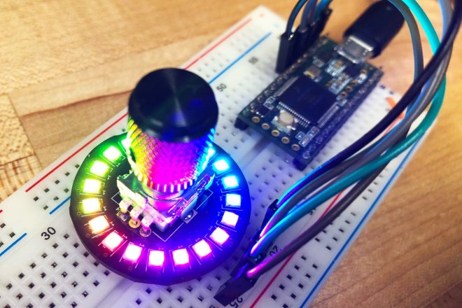
Here’s a neat rotary encoder with a ring of RGB Neopixel LEDs to indicate where its pointing:

2019-06-25T01_44_04.505Z-IMG_4368.

Neopixel Rotary Encoder

What is this?

This is a super-overkill rotary encoder. Not only does it encode in a rotary fashion, it also lights up! It includes a ring of 20 ultra bright and even more ultra tiny Neopixel LEDs. Ever have trouble deciding between different LED colors? Well here you don’t have to. Add this to your next project to give it a brilliant flare in whatever color, or combination of colors, you want.

What can I use it for?

I originally designed this to control digital effects in a guitar. Because the knob would potentially be mapped to several different controls, depending on the active effect, an ordinary potentiometer wouldn’t cut it. What if, for example, in one mode it was set to 50%, and in another it was set to 100%? Enter the LED ring. Now, whenever you change modes, the indicator can reflect the correct value.

But what can it actually do?

Anything! Assuming that ‘anything’ refers to reporting positions from a rotary encoder, acting as a pushbutton, or lighting up. The lights don’t do anything on your own, you need to include some code in your project that takes the encoder signal and does something with the lights. Thankfully, I already wrote that part for you! Here are a few examples of different modes I prepared for you, all of which are included in the example code.

enter image description here

Neopixel Rotary Encoder