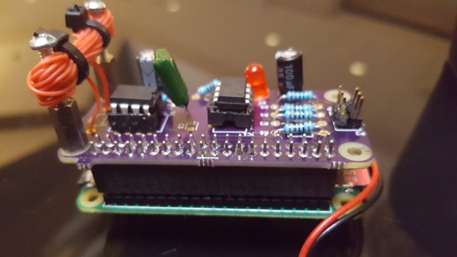
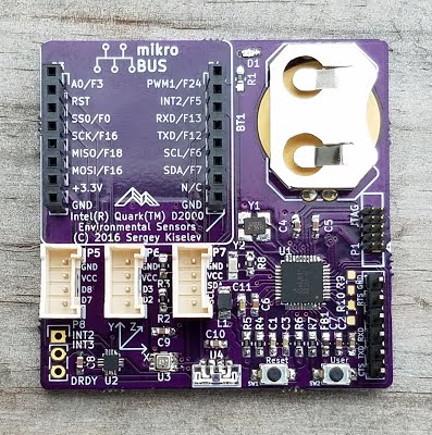
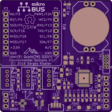
nickjkl created this breakout board to free up some breadboard space:
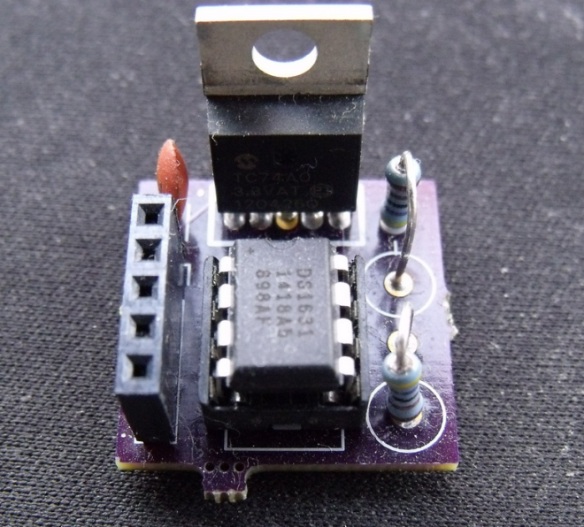
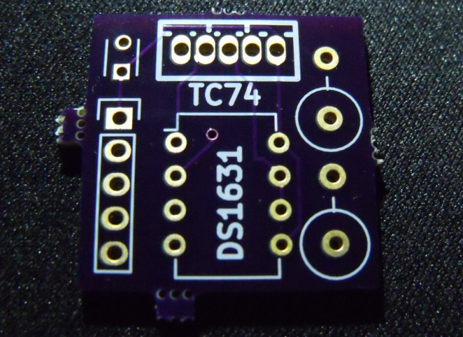
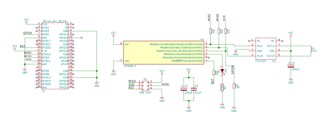
I2C temperature sensor board
contains two I2C temperature sensors: a TC74 and a DS1631 because only one temperature sensor is never enough
KiCad design files and MSP430 Energia sketch example are available on GitHub:
 nickjkl/I2CTempsensor


")