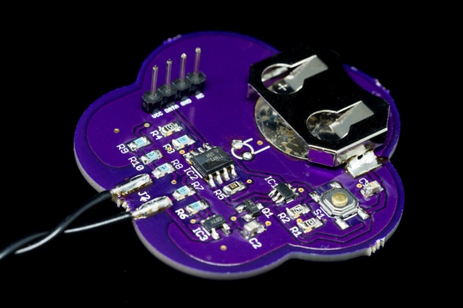
Joe Crop is a creating a real life version of this famous sci-fi device:
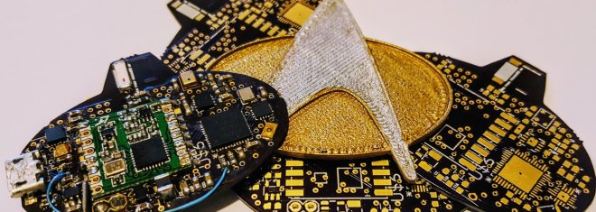
Star Trek Communicator Badge
In the true spirit of Star Trek, this communicator badge is completely autonomous, while fitting in the form factor of an original badge


Star Trek was known for dreaming up technology that was deemed nearly impossible given the limitations of the technology for the day. Having a small badge that could send audio across vast distances seemed out of the realm of possibility during the late 1980’s. This project’s aim is to use modern technology to provide nearly all the features of visionary tech, namely:
– Tap to connect and communicate instantly
– Long range (from orbit to planet surface)
– Small form factor (of an original TNG badge)
– Fully autonomous (no cell phone or base station needed)
– No external power source (i.e. battery powered)
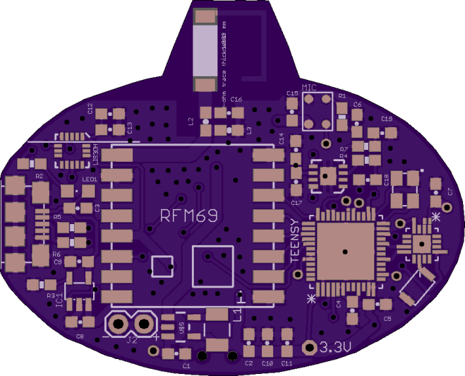
joecrop has shared the board on OSH Park:
Star Trek Communicator v2p1
![]()
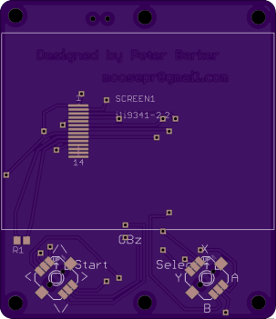
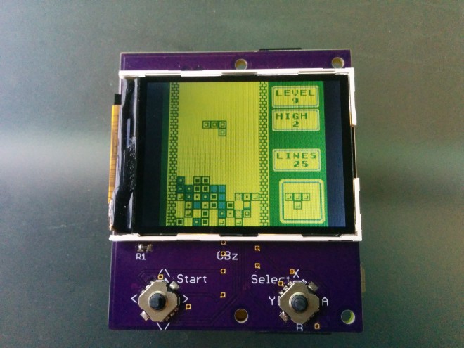 GameBoy Zero, but smaller!