ISL12022M RTC breakout board

From the Pluxx’s Magitech Golem Parts Emporium blog:

C44topVWEAAJj_u.jpg

ISL12022M RTC breakout board

This is a breakout board for the Intersil ISL12022M real-time clock, with optional I²C pull-ups and a CR1225 backup battery. The circuit is based on the design recommended by Intersil, with a few tweaks. It’s the second board I’ve designed so far.

golemparts has shared the project on OSH Park:

ISL12022M RTC Breakout v1.0 A

c44tosaxuaadnik

Order from OSH Park

ISL12022M RTC breakout board

Chronio DIY Watch

 writes on Hackaday:

Chronio DIY Watch: Slick and Low Power

[Max K] has been testing the battery life of his self-designed watch under real-world conditions. Six months later, the nominally 3 V, 160 mAh CR2025 cell is reading 2.85 V, so the end is near, but that’s quite a feat for a home-engineered smart watch

Chronio DIY Watch

Ladder board for simple Automation

chmod775 designed this compact, standalone board to be programmed with a simple visual language:270681483106954815.jpg

Focus

Focus born with the purpose of making a prototype board that simplify every aspect of programming.

Spent the last hour writing down the main concept of the Visual Programming Language for the Focus!  It’s just a simple sketch, but I wanted to share it with you the main reason why I’m building it.

Ladder board for simple Automation

eMMC to SD Card Adapter

20170129_133109-s

From the Intelligent Toasters blog:

Retro CPC Dongle – Part 18

I’ve been working on, replacing the NAND raw flash with an eMMC chip on the CPC2.0 board.

20170129_135450-s

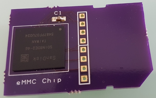
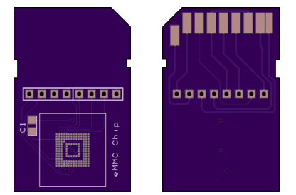
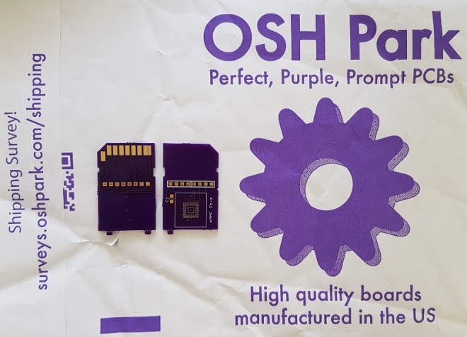
I wrote about raw flash and the challenges of writing a flash translation later in part 16 of this series. After some research, I concluded that the eMMC interface looked exactly like the much more common SDCard interface, albeit that the interface can be run with an 8-bit width. SDCards are limited to 4 bits by the physical pin count. Taking a gamble I created a board to test this new eMMC chip. I created a fake SDCard!

20170129_135518-s

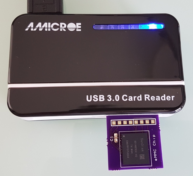
This fake card allowed me to check very quickly if my assumptions were correct both at a hardware and a firmware level. I wanted to be sure that it was possible to interface the eMMC via 4 bits, rather than the full 8 bits and be sure the firmware instructions were the same between these two technologies.

Intelligent-Toasters has shared the board on OSH Park:

emmc.zip

screenshot-at-2017-02-15-21-04-11

Order from OSH Park

eMMC to SD Card Adapter

Vertically Mounted Arduino-Compatible Board

Clovis Fritzen designed this Arduino-compatible, vertically-mountable board that exclusively uses through-hole components:

arduino-vertical-676x507

Vertically mounted Arduino for Breadboard

I personally love the concept of electronic boards connected in “slots” (vertically attached to a horizontal board), like most industrial-grade PLC’s or even our desktop’s expansion cards (video, sound memory): it saves a lot of space and adds more functions to the system, all at once!


The PCB is for sale on Tindie:

tindie-logo2x

Vertically mountable Arduino – PCB only

This is an Arduno-Nano compatible controller that can be vertically mounted to bredboards and boards


Vertically Mounted Arduino-Compatible Board

Snowbot

Dan Hienzsch a holiday project to build a little Snowbot with an adjustable speed larson scanner for an eye:

snowbot_v1_prototype-2

Snowbot Ornament Project

When I started thinking of this project, I wanted to make something that included a bit of the basics and something more advanced. It had to be battery powered, and most importantly, I wanted to make sure it went against the grain of everything needing a microcontroller. Thus Snowbot was born.

Photos from the Hackaday.io project:

RheingoldHeavy has shared the board on OSH Park:

Snowbot_2015_Rev1

snowbot_revised_silkscreen_preview

Order from OSH Park

Snowbot

LED Matrix Generator for EAGLE

Ted Yapo is designing a display for his  LED Oscilloscope Mk. II and decided to automate the process:

6979361486485114739

16×32 Display Design

I painstakingly drew the schematic for 512 LEDs in this display, then endured the drudgery of laying out the board. The whole process took about 45 seconds. Yes, I wrote a few Eagle User Language Programs (ULPs) (elapsed time after the scripts were written and debugged). The previous time I wrote one was last century to lay out a circular LED clock face. I figured it was about time I regained those skills.

8920781486146501489-1

The EAGLE ULPs are on GitHub:

led-matrix-generator

 Eagle scripts for LED matrix display generation

LED Matrix Generator for EAGLE

Rotary Encoder Breakout Board

UPDATE: Check out the new version with pull-up resistors

img_20170211_233051

I designed this simple breakout board in KiCad to make it easier to put a rotary encoder on a breadboard.   The KiCad symbol and footprint for the SparkFun rotary encoder was created by mcous on GitHub.  I used an updated version with corrected pin numbering.

img_20170211_230723

Here are the rotary encoders that I’ve verified to fit:

img_20170211_233439

The design files are available on GitHub:

Screenshot at 2017-02-14 20-58-40.png pdp7/rotary-encoder-breakout

The board is shared on OSH Park:

SparkFun Rotary Encoder Breadboard Adapter

e1911a0b6c7595c4cd7a05c4806f83bf.png

Order from OSH Park

Rotary Encoder Breakout Board