From zakqwy on Hackaday.io:
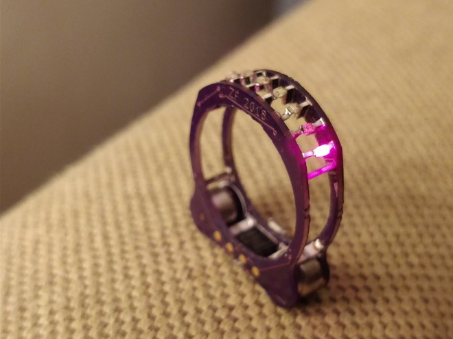
Cyborg Ring
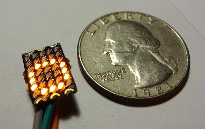
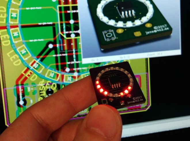
cordwood + smt + jewelry + blinkies + zinc-air batteries
This project evolved from Splinter, the SMT cordwood project I did last summer/fall. The ring is powered by tiny size 10 hearing aide batteries which should give 4-6 weeks of intermittent use, once I come up with a design that doesn’t break after a few days of wear and update the firmware to put the ATtinyx5 to sleep. The first rev (labelled ‘blink-ring’) used deep red 650nm LEDs. Searching for particular component lengths gave me an excuse to use strange 0508 resistors. And somehow, this is my first Charlieplexing project. Yaay novelty soldering!