CANoolder: CAN to 3.3V interface

Colin O’Flynn of NewAE designed this simple CAN to 3.3V logic level interface:
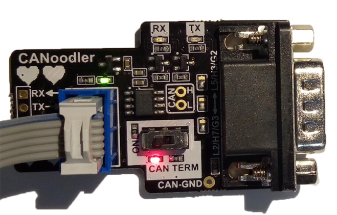
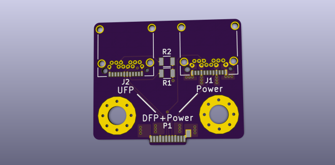
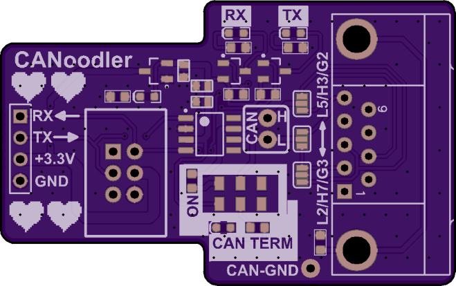
CANoodler_assembled.png

CANoodler

CANoodler is a simple CAN (not CAN-FD) interface, which provides logic-level 3.3V output. It’s designed to be used with microcontrollers that have CAN blocks inside them, and in particular uses a pinout on some ChipWhisperer CW308 (UFO) Target boards.

It’s kinda nice (I think anyway) since it has these features:

  • LEDs for TX/RX (uses MOSFET to drive LEDs so doesn’t slow your I/O pins down).
  • Reverse-polarity protection on 3.3V input.
  • Switch for CAN termination on/off with LED feedback.

The design files are available on GitHub:

newaetech/CANoodler

Screenshot from 2017-08-28 01-38-11

coflynn has shared the board on OSH Park:

CANoodler – CAN to TTL Interface

bf472e82dc546a6961d4fb364dbf77c2.png
Order from OSH Park

CANoolder: CAN to 3.3V interface

PD Buddy Wye

Clayton G. Hobbs previously created the USB-C PD Buddy Sink and has a new USB-C related project on Hackaday.io:
6191961503944695328

PD Buddy Wye

Power/data splitter for PD Buddy Sink

5861941503944748230

As of version 1.1.0 of its firmware, PD Buddy Sink can do USB Power Delivery negotiations while in Setup mode, making requests for new voltages and currents in real time based on user input via a USB CDC-ACM virtual serial port. To make full use of this feature, users need to be able to connect power and data to the PD Buddy Sink simultaneously. This board makes that possible, even with a computer that lacks USB Power Delivery output.
2801061502051112285
PD Buddy Wye

6502 Expansion Board for Z80 Homebrew

Alasdair Allan writes on Hackster.io:

6502board.png

A 6502-Based Expansion Board for a Z80-Based Homebrew Computer

Up till now I haven’t seen a 6502-based board, and now I’m seeing both at once—a 6502-based expansion board for a Z80-based homebrew computer.   Ben Chong, over at Ancient Computing, has done a lot of work around Spencer Owen’s RC2014 Z80 microcomputer kit, including designing an improved Z80 processor card and a 16550 UART board.

rc2014_6502

the 6502-based CPU board he’s put together is by far the most impressive. On his site Ben outlines his design process, and deep dives into how he got a 6502-based card to talk to a Z80-based system. This isn’t a trivial feat as the two processors have very different design philosophies—with the 6502 using a strict synchronous bus, and the Z80 using a loosely asynchronous bus. He then talks about software before doing some crude performance testing.

The hardware design files are available on GitHub:

ancientcomputing/rc2014

Screenshot from 2017-08-28 01-38-11

ancientcomputing has also shared many projects on OSH Park:

eb4249df5cf14029b95feea42fcc3f70.png

6502 Expansion Board for Z80 Homebrew

The Road from AXIOM Beta Developer Kit to Production Camera

From Sebastian of the Apertus Open Source Cinema Camera project:

axiom-beta-dev-kit01.jpg

The Road from AXIOM Beta Developer Kit to Production Camera

Developer Kits have been shipping for some time now and we are aware that the most pressing question for many of you is “When will the AXIOM Beta evolve from a Developer Kit to being a production ready camera?” This article should help to answer that question, but keep in mind that the camera has been carefully designed to evolve constantly.


The Road from AXIOM Beta Developer Kit to Production Camera

Workshop: Assembling the Tinusaur Kit in Varna, Bulgaria

This Saturday, September 2nd, we will have one day workshop for assembling the Tinusaur kits for those who supported our Indiegogo crowdfunding campaign. It will take place in Varna, Bulgaria, our host will be VarnaLab – the local hackerspace. We will learn the basics of electronic components, microcontrollers – ATtiny85 in particular and, of course, […]

via Workshop: Assembling the Tinusaur Kit in Varna, Bulgaria — The Tinusaur Project

Workshop: Assembling the Tinusaur Kit in Varna, Bulgaria

Battman Battery Management System

From Raphael Chang:

battman_v4.1.jpg

Battman Battery Management System

As part of the fully custom electric longboard I am building, I designed a battery management system (BMS) for a 12 cell lithium ion battery pack. The BMS, named “Battman”, is meant to monitor both Lithium Polymer cells (LiPo) and Lithium Iron Phosphate cells (LiFePo4), and it can protect the batteries against undervoltage, overvoltage, overcurrent, and overtemperature.

It also has an integrated charging circuit that can perform constant current/constant voltage charging of the cells up to 6A, while performing balancing of the cells at 100mA. In addition, it functions as the main power switch of the longboard system, and includes a precharge circuit to limit inrush currents. Finally, the BMS does current measurements for coulomb counting, and performs state-of-charge calculations.

The project is shared in these GitHub repos:

Andrius has shared the board on OSH Park:

Battman lithium ion battery management system

30309238d822b3db51a3d7f7553d3e59.png

Order from OSH Park

Battman Battery Management System

Making A Pickit 3 Clone

509.jpg

Making A Pickit 3 Clone

After using the Microchip tools to program and debug the projects I work on, I wondered about creating my own programming/debugging module that I could put on my own boards – just like Microchip does with their starter kits and such.

pcb_1.jpg

I decided to use the open-source EDA program Kicad to design a 4 layer SMD project. I had only used it for 2 layer PTH designs previously, but wanted to see how it would do in something a little more complex than the ones I had already done. Here is a link to the completed Kicad project files

Sybex23 has shared the board on OSH Park:

PICKIT 3 Programmer

979e83d73b177814d75f1febb72135ea.png

Order from OSH Park

Making A Pickit 3 Clone