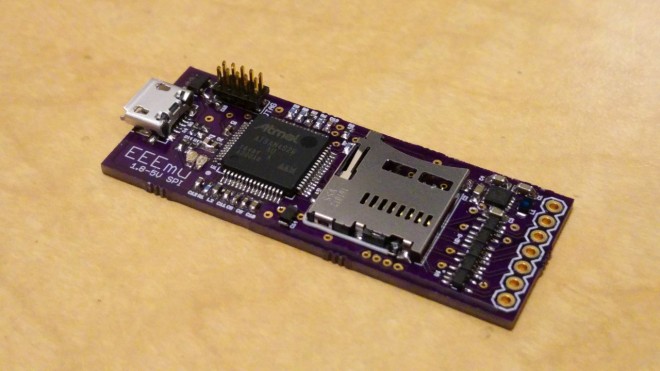
The EEEmu SPI emulates any Serial Peripheral Interface Bus EEPROM or Flash memory chipsets up to an interface speed of 25MHz. It also supports any supply and interface voltage between 1.8 to 5 Volts and can be configured to support even the largest of memory sizes.
This repository contains configurations for all the currently supported EEPROM and Flash chips for the EEEmu SPI:
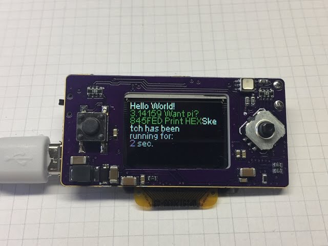
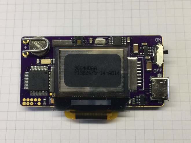
In the last entry for the Timed LED Lighting Controller, I realised that there are no working examples of an I²C driver for the ATtiny20. I then had to work through the data sheet to implement my own. With that done, I could then start on the application firmware and get the board really working. So this is where my proof of concept becomes the prototype.
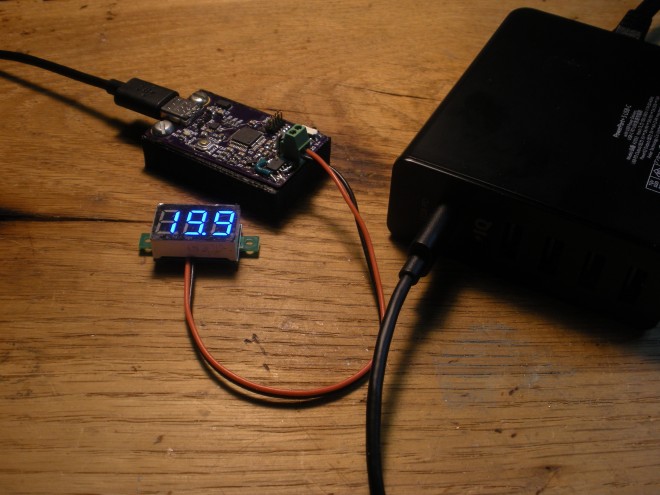
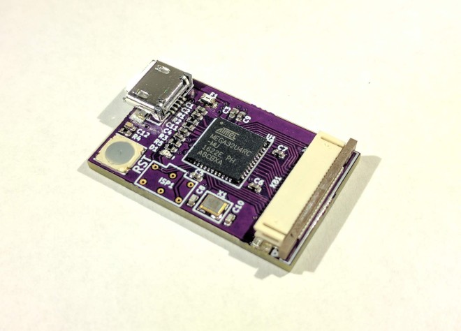
USB Power Delivery is a cool standard for getting lots of power—up to 100 W—from a USB Type-C port. Being an open standard for supplying enough power to charge phones, laptops, and just about anything else under the sun, USB PD is poised to greatly reduce the amount of e-waste produced worldwide from obsolete proprietary chargers. Unfortunately, like all USB standards, it’s quite complex, putting it out of reach of the average electronics hobbyist.
PD Buddy Sink solves this problem, letting any hacker or maker use USB PD in their projects. Think of it as a smart power jack. To use it, first configure a voltage and current via the USB configuration interface. Then whenever the Sink is plugged in to a USB PD power supply, it negotiates the power your project needs and provides it on the output connector.
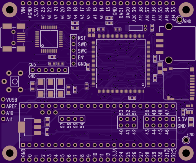
The KiCad design files are available on his website:
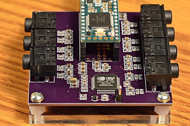
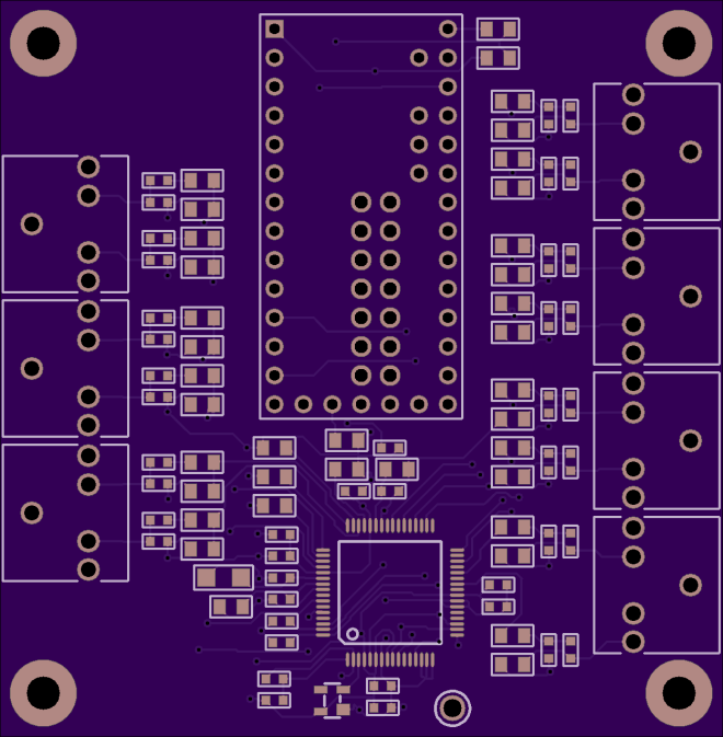
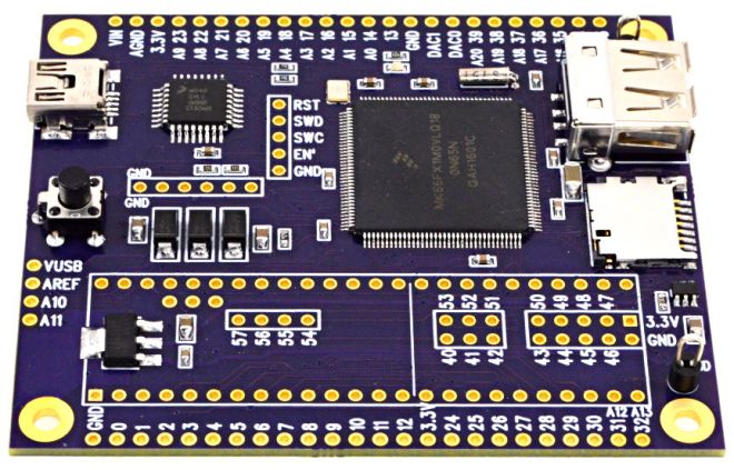
Some projects need a lot of audio I/O. Maybe you’re doing positional audio sound effects (using the 8-tap delay effect) where ordinary stereo or even 5 channel “surround” isn’t enough? Maybe you’re making the ultimate Eurorack synthesizer module? Or you just want a lot of signals, because you can!
Here’s a board for the Cirrus Logic CS42448 chip, which provides 6 inputs and 8 outputs. All are high quality audio, and all work simultaneously.
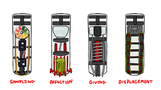
This summer, I am once again diving into designing mechanical personality quirks. I’ll be investigating new and exciting ways for my robot, NoodleFeet to interact with the world. This time, my focus is the wet, tingly and preferential aspect of TASTE.
From now until the end of August, my goal is to produce four different tasting modules that each demonstrate some aspect of sampling or preference. You could think of them as the “four tasters of the apocalypse”
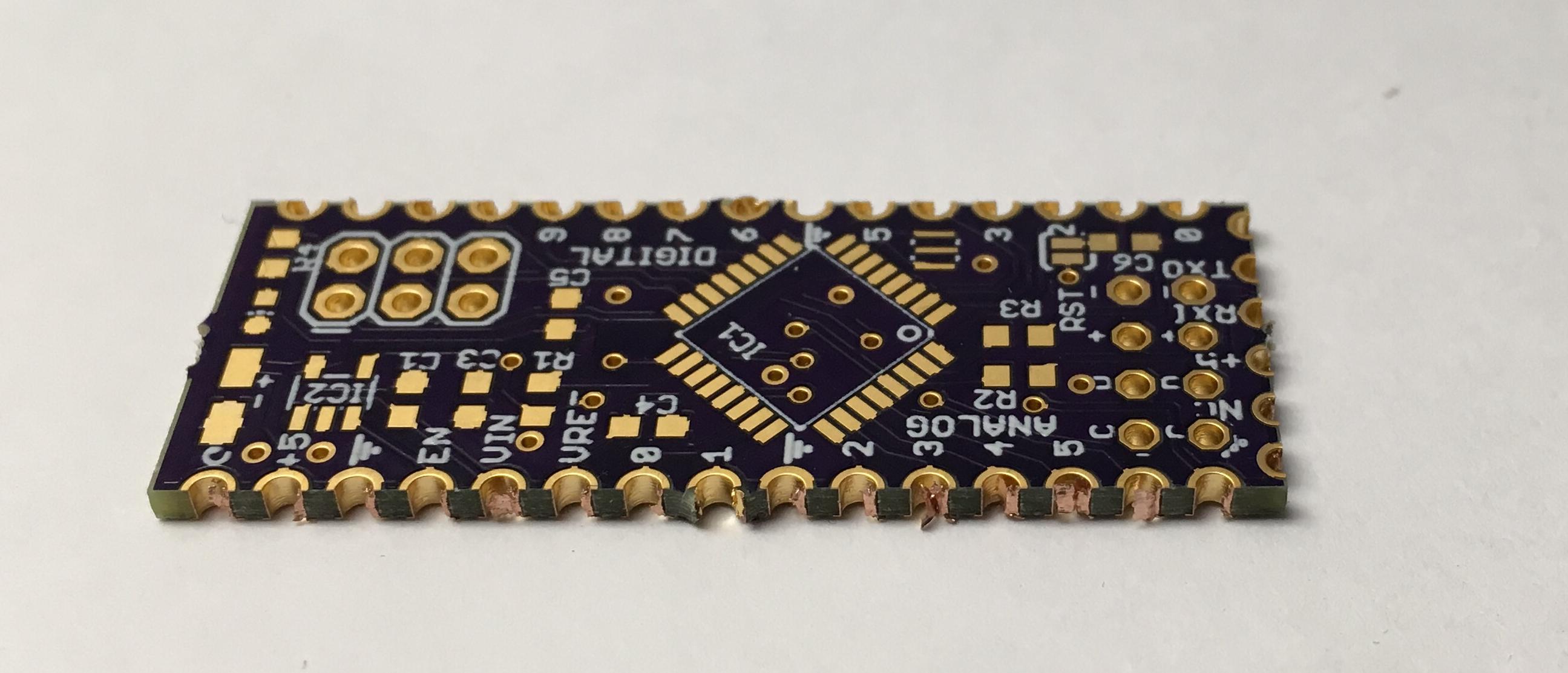
Castellations are small plated edges, typically used for making circuit boards into small PCB modules. These are often seen on wireless modules, such as the ESP8266-12E.
While we don’t offer full support for castellations, they can be fabricated if you don’t mind a few minutes of rework and verification of the PCBs.
Design Considerations
It’s helpful to include a fallback hole near the edge. The ESP8266-12E boards, are a great example here. The extra via allows easy connecting of wires for rework, and makes it easy to salvage a module if the fabricated PCB doesn’t turn out perfectly.
Castellations are simple to call out in most design tools. Simply include a via on the PCB, so the board outline goes through it.
However, due to our panelization process, the castellated vias must be indicated with round pads for copper and stop mask. The pads must also not extend more than 40 mil from the board edge. Square pads or pads that extend far beyond the edge will be trimmed, and the via will not be plated.
It’s also helpful to use a 10 mil wide line for the board outline. With our milling tolerance of 5 mil, this provides a good visual indicator of where the physical board edge might be. The fabricated edge can be anywhere within that line. This is very helpful for fine-pitch castellations with smaller holes.
Callout as seen in a design tool
Rectangular castellations can be made by using vias with round pads as noted above, and adding overlapping rectangular SMD pads. Since these pads are inside the board outline, they will not be trimmed, and will provide additional area for soldering (see below for example).
Cleaning up the final boards
We make a best-effort to minimize support tabs on castellated edges, but it sometimes happens. In these cases, you’ll need to file the tab off of your edge.
Additionally, the via plating may not be fully removed during the milling process. In some cases it’s smashed next to the edge, where it can cause unwanted connectivity between vias. In others, it’s smashed inside the via, where it will prevent good solder flow. A fine point file or hobby knife will help remove excess plating.
An unreworked castellated PCB, with visible plating stubs
Another version, with tabs on castellated edge and modifications for rectangular pads

 EEEmu/Supported-Devices