Raspberry Pi CAN-bus HAT for the Omzlo IoT platform

From Omzlo Electronics:

omzlo-pi-master-rpi.jpg

A Raspberry Pi CAN-bus HAT for the Omzlo IoT platform

In a previous blog post, we described “SKWARE” our revised Arduino-compatible IoT modules. These nodes are designed to be connected together in a daisy-chain fashion with a single cable that brings both DC power and CAN-bus networking. The voltage transported in the cables is not 5V (or 3.3V) but rather 12V or 24V to work more comfortably over long distances, potentially reaching 300 meters (1000 feet). You can think of it as a poor-man’s PoE.

omzlo-pi-master-diagram

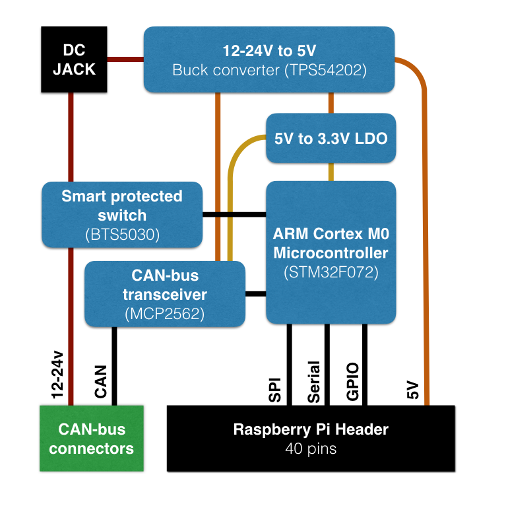
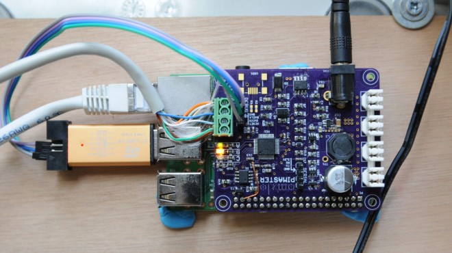
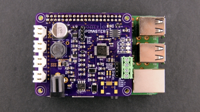
This network of connected nodes is designed to be monitored and controlled by a “master node”, which injects the necessary 12V/24V DC, provides node management services and a web interface for network administration. While the IoT nodes are based on an Arduino-style microcontroller, the “master node” requires a bit more power. In this context, the ubiquitous Raspberry Pi with its GPIO header seems like an ideal candidate for that role and we decided to see if we could build a “master node” by augmenting a Raspberry Pi with an appropriate add-on board. These add-on boards are called “HATs” (for “Hardware Attached on Top”) and we called our first prototype the “Pi Master HAT”.

omzlo-pi-master-network

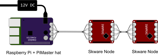
The drawing below illustrates the general structure of our network. A Raspberry Pi equipped with our “Pi Master HAT” controls a network of 2 (or more) daisy-chained nodes, like the SKWARE.

omzlo-pi-master-debug

Raspberry Pi CAN-bus HAT for the Omzlo IoT platform

LoFive RISC-V board now on GroupGets

LoFive RISC-V dev board designed by Michael Welling with KiCad is now on GroupGets:

8abaa9b3ce3ab723089fdb42a00d1b5a008dad5b

LoFive is a small board based on the SiFive Freedom E310 open source SoC

LoFive_LED

Specifications

  • MCU – SiFive Freedom E310 (FE310) 32-bit RV32IMAC processor @ up to 320+ MHz (1.61 DMIPS/MHz)
  • Storage – 128-Mbit SPI flash (ISSI IS25LP128)
  • Expansion – 2x 14-pin headers with JTAG, GPIO, PWM, SPI, UART, 5V, 3.3V and GND
  • Misc – 1x reset button, 16 MHz crystal
  • Power Supply – 5V via pin 1 on header; Operating Voltage: 3.3 V and 1.8 V
  • Dimensions – 38 x 18 mm (estimated)
  • License – CERN Open Hardware Licence v1.2

LoFive-Schematics-600px

The design files are available on GitHub:

mwelling/lofive

LoFive RISC-V board now on GroupGets

CANoolder: CAN to 3.3V interface

Colin O’Flynn of NewAE designed this simple CAN to 3.3V logic level interface:

CANoodler_assembled.png

CANoodler

CANoodler is a simple CAN (not CAN-FD) interface, which provides logic-level 3.3V output. It’s designed to be used with microcontrollers that have CAN blocks inside them, and in particular uses a pinout on some ChipWhisperer CW308 (UFO) Target boards.

It’s kinda nice (I think anyway) since it has these features:

  • LEDs for TX/RX (uses MOSFET to drive LEDs so doesn’t slow your I/O pins down).
  • Reverse-polarity protection on 3.3V input.
  • Switch for CAN termination on/off with LED feedback.

The design files are available on GitHub:

newaetech/CANoodler

Screenshot from 2017-08-28 01-38-11

coflynn has shared the board on OSH Park:

CANoodler – CAN to TTL Interface

bf472e82dc546a6961d4fb364dbf77c2.png
Order from OSH Park

CANoolder: CAN to 3.3V interface

PD Buddy Wye

Clayton G. Hobbs previously created the USB-C PD Buddy Sink and has a new USB-C related project on Hackaday.io:
6191961503944695328

PD Buddy Wye

Power/data splitter for PD Buddy Sink

5861941503944748230

As of version 1.1.0 of its firmware, PD Buddy Sink can do USB Power Delivery negotiations while in Setup mode, making requests for new voltages and currents in real time based on user input via a USB CDC-ACM virtual serial port. To make full use of this feature, users need to be able to connect power and data to the PD Buddy Sink simultaneously. This board makes that possible, even with a computer that lacks USB Power Delivery output.
2801061502051112285
PD Buddy Wye

6502 Expansion Board for Z80 Homebrew

Alasdair Allan writes on Hackster.io:

6502board.png

A 6502-Based Expansion Board for a Z80-Based Homebrew Computer

Up till now I haven’t seen a 6502-based board, and now I’m seeing both at once—a 6502-based expansion board for a Z80-based homebrew computer.   Ben Chong, over at Ancient Computing, has done a lot of work around Spencer Owen’s RC2014 Z80 microcomputer kit, including designing an improved Z80 processor card and a 16550 UART board.

rc2014_6502

the 6502-based CPU board he’s put together is by far the most impressive. On his site Ben outlines his design process, and deep dives into how he got a 6502-based card to talk to a Z80-based system. This isn’t a trivial feat as the two processors have very different design philosophies—with the 6502 using a strict synchronous bus, and the Z80 using a loosely asynchronous bus. He then talks about software before doing some crude performance testing.

The hardware design files are available on GitHub:

ancientcomputing/rc2014

Screenshot from 2017-08-28 01-38-11

ancientcomputing has also shared many projects on OSH Park:

eb4249df5cf14029b95feea42fcc3f70.png

6502 Expansion Board for Z80 Homebrew

The Road from AXIOM Beta Developer Kit to Production Camera

From Sebastian of the Apertus Open Source Cinema Camera project:

axiom-beta-dev-kit01.jpg

The Road from AXIOM Beta Developer Kit to Production Camera

Developer Kits have been shipping for some time now and we are aware that the most pressing question for many of you is “When will the AXIOM Beta evolve from a Developer Kit to being a production ready camera?” This article should help to answer that question, but keep in mind that the camera has been carefully designed to evolve constantly.


The Road from AXIOM Beta Developer Kit to Production Camera

Hackaday Prize Entry: MappyDot, a Micro Smart LiDAR Sensor

UPDATE: now available for sale on the Tindie

[Blecky]’s entry to the Hackaday Prize is MappyDot, a tiny board less than a square inch in size that holds a VL53L0X time-of-flight distance sensor and can measure distances of up to 2 meters. MappyDot is more than just a breakout board; the ATMega328PB microcontroller on each PCB provides filtering, an easy to use I2C interface,…

via Hackaday Prize Entry: MappyDot, a Micro Smart LiDAR Sensor

Hackaday Prize Entry: MappyDot, a Micro Smart LiDAR Sensor