Dock for Onion Omega2

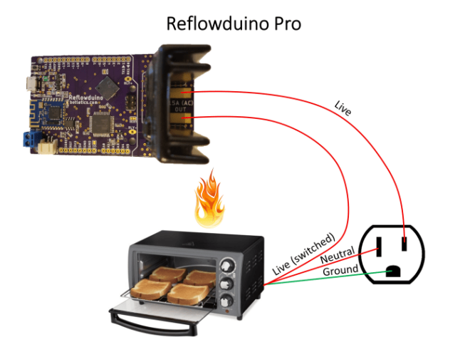
Valerio Backslashnew has designed a small dock for the Onion Omega 2 and 2+:

collage

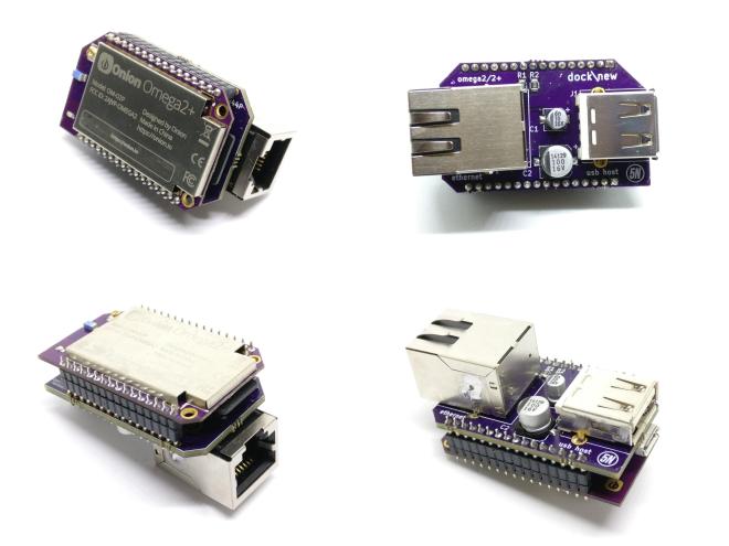
My Omega 2/2+ dock\new

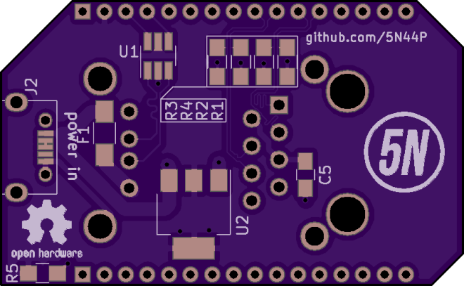
I needed the smallest dock i could do, that featured:

  • Ethernet
  • Type A USB host
  • Micro USB for power

Here’s what i came up with, i called it dock\new.

layout

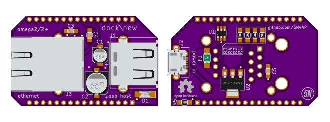
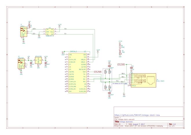
It has an onboard linear voltage regulation (i didn’t bother going with a switching one for such low power), magnetics integrated in the RJ45 connector to save space, USB host ESD protection (diode array), USB host PTC fuse.

On the left side there is the RJ45 connector and nothing on the back side of the board, so that you can easily access the MicroSD card on the Omega 2+.

On the right side (the antenna side of the omega) you have the USB type A connector, facing outwards, and the microusb connector for power, facing inwards.

The project is open source (CC-BY-SA 4.0), and the KiCad schematics, board layout and the other files are available on GitHub:

5N44P/omega-dock-new

schematic.jpg

5N44P has shared the board on OSH Park:

omega-dock-new.kicad_pcb

d9fc59e0f065521992ed510307a3f2bd.png
Order from OSH Park

Dock for Onion Omega2

reDot Smart 5×7 LED Matrix

Alex on Hackaday.io is working on a smart miniature (DIP6) 5×7 LED Matrix:

5081641517597723580.JPG

reDOT_smart

This project is based on my #reDOT project. Basicly it is a 5×7 SMD LED Matrix an a microcontroller on one PCB. I started wirh 0201 LEDs (see first project log), but this was not reliable. So a second version with 0402 is in development. 0402 LEDs do have some benefits over 0201:

  • bigger and you can solder them better
  • cheaper
  • more colors availible

The microcontroller (a low coast STM8) drives all LEDs directly with multiplexing. For controlling a UART interface is available. The dimensions are like a DIP-6 package. For easy connection of multiple PCBs, the pads are castellated. Also the supply rails are available on both sides. So multiple of these display can be soldered together to a bigger display without the need of additional wiring.

reDot Smart 5×7 LED Matrix

LED ring

Jens Hauke designed this charlieplexed 20 LED blinker controlled by an ATTiny45 for the Hackaday Coin Cell Challenge:

156251514462780263

LED Ring

This is a small blinky with 20 LEDs powered by one CR2032 coin cell
and with an ATTiny45 brain. The firmware is written in plain C and
compiled with the avr-gcc toolchain. The PCB is a two layer design made
with KiCad.
Space efficient daisychained LED placing with shared anode/cathode soldering pads.

Firmware and gerbers are available on GitHub:

jensh/attiny-20led-ring


Jens has shared the board on OSH Park:

LED 20 Ring ATTiny

65a7204f0dcd3a7d1b3f36c7370cb7af

Order from OSH Park

Here is a video of the LED in action:

LED ring

Snowbot

A holiday project by Dan Hienzsch (@rheingoldheavy) to build a little Snowbot with an adjustable speed larson scanner for an eye:

2999791454992848983.jpg

Snowbot V1.0

The Snowbot has three major subsystems: Power and Timer and Display.

Power Subsystem

The power subsystem uses a 3.7V LiPO battery boosted to 5V with an SC4503 boost converter to power the fully analog circuit. It requires a set of passive components in order to generate the higher voltage.

3145851454992895613.jpg

Timer Subsystem

The timer subsystem is comprised of a 555 IC that generates a clock signal. The speed of the clock is adjusted by twisting the potentiometer (the nose of the snowbot). The clock signal ticks through the outputs of a CD4017 decade counter, lighting each LED in sequence, then moving back through them again.

8990681454993097528

Display Subsystem

The display subsystem involves taking the output of the CD4017, and directing it to six red LEDs in the form of a larson scanner. In addition to lighting the LED, the current also charges a 22uF capacitor through a diode. When the output moves to the next LED, the cap discharges through a 2.2K resistor (part of a resistor network), fading the LED out gracefully.

Snowbot

1bitsy and Black Magic Probe

The 1bitsy and Black Magic Probe are now available in our store:

1bitsy_v1_0a_legend_1024x1024

1Bitsy STM32F415 Development Board

Open-Source Miniature Breadboard Friendly ARM Cortex-M4F Dev Board with 1MB Flash, 196kB RAM, 168MHz, floating point and more.

bmpm_v2_1c_purple_top_1024x1024

Black Magic Probe V2.1

Plug and Play JTAG/SWD USB programmer and debugger with a built in GDB server and TTL level UART to USB adapter.


1bitsy and Black Magic Probe

How Fast is Your Fidget Spinner?

From Ken Olsen of The Maker’s Box:

How Fast is Your Fidget Spinner?

You never know what people will do with your ideas, and it is always fun to see someone do something I would have never thought off with them.  I got a video from someone who built my Programmable Fidget Spinner, and used a leaf blower to see how fast they could get it to go.  Fortunately, they were wearing safety glasses, and no, it didn’t come flying apart.  It did, however, start displaying erratically at about 3600 RPM (the fastest I can get it by hand is just under 2000 RPM).

So, what is going on?  TLDR: I figured it out and fixed it, and here is proof.

How Fast is Your Fidget Spinner?

Reflowduino: Circuit Board Assembly for Everyone

Timothy Woo has launched a Indiegogo campaign to manufacture his open-source, Arduino-compatible, wireless PCB reflow oven controller:

vwqlvw1alqs19g9mq16x.jpg.png

Reflowduino: Circuit Board Assembly for Everyone!

Reflowduino is the first completely open-source, Arduino-compatible reflow oven controller of its kind that enables practically anyone to assemble their own beautiful circuit boards at home!

Reflowduino comes loaded with features, all in a compact Arduino-compatible package, with full documentation, example code, demo app, and comprehensive wiki on Github.

ecriw1wwk9mpio5pmbz4

Reflowduino is designed to be extremely easy to use! The general concept is to switch the power of the appliance on or off with a solid-state relay as shown below, measuring the temperature by placing the thermocouple tip inside the oven during the whole process.

If nothing else, please share this campaign to your friends, family, and anyone who might be interested on social media! Remember that every view counts for me, and I’m depending on you to make this happen!

arynyhrvcfd87k9omiwx

Reflowduino: Circuit Board Assembly for Everyone

LTE NB-IoT Shield for Arduino

From Timothy Woo on Hackaday.io:

8302141510267404941.jpg

LTE NB-IoT Shield for Arduino

This open-source LTE shield uses SIMCOM’s SIM7000-series modules with the latest LTE CAT-M technology to allow Arduino users to painlessly connect their low-power IoT devices with the next-generation cellular technology!

6990071510267413269

NB-IoT is also available for many countries (but sadly not in the USA yet) simply by swapping out to a different SIM7000 module version. Luckily SIMCOM made it super easy to integrate this module because most of the AT commands are identical to previous version, and Adafruit has a wonderful library for their FONA 2G and 3G products. Check it out and help make this happen!

3454341510977654311

You can view the latest code and design files here on my Github page: https://github.com/botletics/NB-IoT-Shield. Note: The hardware works great but software is still under development! I plan on launching an Indiegogo campaign when I get a fully-working prototype, so stay tuned for updates!

LTE NB-IoT Shield for Arduino

Arduino Neural Network Robot

Sean Hodgins created an Arduino-based robot that avoids light by navigating using a neural network:
4863551509384902904
This project is meant to teach about utilizing neural networks in robotic platforms. There will be a 3 part video series on the Make YouTube channel on building the robot. It will start with prototyping and design, then move onto assembly and testing, and finally programming and running the neural network. You will be able to follow along and make your own robot in the end.

Part 2: Soldering and Assembly


Arduino Neural Network Robot

Grid-EYE 8×8 Infrared Camera

From Jeremy S. Cook on the Tindie blog:

grid-cam.jpg

Grid-EYE 8×8 Infrared Camera

Thermal imaging has remained an interesting, if costly, technology for some time. One lower cost option is the the Grid-EYE sensor from Panasonic. While it has a resolution of only 8×8 pixels, it’s priced in the low double digit range, making it an ideal candidate for budget projects. If you’d like to add it to your build, Pesky Products has a has a breakout available that allows it to be used with the I²C protocol.

grid-eye

Xose Pérez, after finding this sensor and breakout on Tindie, which he (correctly) considers “a great place to find uncommon electronic components or weird/interesting boards,” decided to make his own low-resolution IR camera. At only 64 pixels of resolution, it’s not as capable as more expensive units, but it could still be very useful for getting a general idea of what is hot and cold in a room/environment. The case is made out of slices of acrylic, paper, cardboard, and MDF, giving it a very unique look. It also features a small screen to display supplemental information, and a simple button/switch  interface.

Grid-EYE 8×8 Infrared Camera