After 20+ years of programming, I wanted to get some understanding of the electronics that make my career possible.
I had built the basic individual logic gates with transistors on a breadboard, but to build anything meaningful I needed loads of them and so I bought a somewhat random collection of logic chips on Amazon which introduced me to the 7400-series and the concept of datasheets.
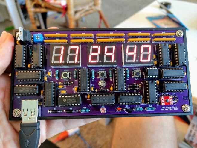
After a few simple projects I wanted to build something more useful: a quartz clock with LED display.
I took a 5 month sabbatical from work and software in general to get into digital electronics, and somehow managed to build my son an actual clock (no uC or code) using @digikey, @kicad_pcb, @oshpark and @Hacksterio.
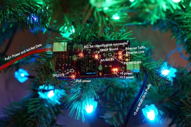
The lighted tree in the video above gets both the power and data for its RGB LED pixels using a single Ethernet cable. Power for the pixels is supplied from an Ethernet switch using the 802.3at PoE+ standard. Data for the pixels comes from software running on a PC that generates Art-Net packets at 40 Hz. Each Art-Net packet contains the RGB levels for all the pixels on the tree. Let’s take a closer look at the technical details and how this tree came into existence.
A few weeks ago, I wrote a post where I reversed engineered some Philips Color Kinetics iColor Flex RGB LED string lights. These lights require an AC power data supply that supplies 24 volts to power the pixels and transforms DMX or UDP packets of pixel data into the protocol used by the pixels. In addition to the power supply, the pixels require a proprietary leader cable to connect them to the power supply.
In a typical setup, you have to run AC mains power and Ethernet data to the power supply then run the leader cable to the pixels. To avoid having a large stack of power data supplies in larger setups, Color Kinetics makes a rack mount power supply that can power up to eight strings of lights. This rack mount power supply still requires a leader cable for each string of lights.
I’ve been wanting to build an 802.3af/at/bt Power over Ethernet design for a few years now and have always come up short on ideas and then it hit me, what if the Ethernet cable could connect closer to the pixels in the photo above? With a small box of electronics between the Ethernet cable and the connector on the end of the pixels, the pixels could receive both power and data from the Ethernet switch. No more AC mains wiring and no more proprietary leader cables.
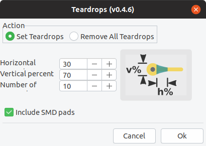
This action plugin adds and deletes teardrops to a PCB.
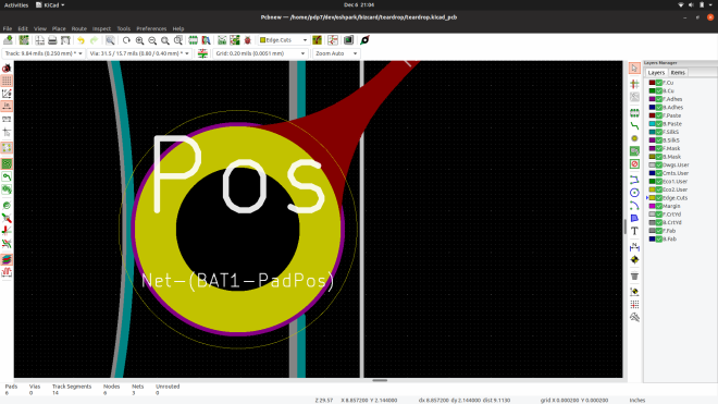
This implementation uses zones instead of arcs. This allows to comply with DRC rules by simply rebuild all zones. You can also modify their shape by simply modifying the zone outline (like any other zone). Teardrops created with this script use a specific priority (0x4242) to be recognized as teardrops.
You also need to be careful that there is not copper on the same layer too close to the zone. For example, the text was too close to the teardrop zone on this via, so I moved the text down and the zone now fills correctly:
An open GitHub issue is that the teardrop zone does not align perfectly for SMD pads that are not circles (like rectangles, squares, rounded rectangles). The work around I used was to move the zone after it is filled to align with my SMD pad:
I hope you have fun with this plugin and leave a comment if you use it your own design!
And finally, receiving the biggest applause was Linux-on-Badge: this team used all the badge hacking tricks in the book. The hardware component was a 32 MiB SDRAM cartridge by [Jacob Creedon]. The default badge SOC FPGA bitstream was entirely replaced in order to support a minimalist Linux. Much of the development was done on [Michael Welling]’s computer, guided by the precedence of a LiteX project putting Linux on the Radiona ULX3S. This is a true success story of Supercon collaboration as the team (including [Drew Fustini], [Tim Ansell], [Sean Cross], and many others) came together and worked late into nights, drawing from the massive body of collective expertise of the community.
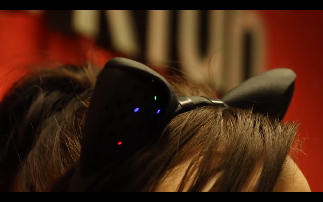
At the beginning of this year I began prototyping an audio reactive headband to wear in my everyday life, like while dancing with my dog in my lab listening to Legend of Zelda dubstep.
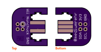
A few weeks ago I saw this post by my favorite Engineer/Maker/FashionTech Designer/Roboticist Anouk Wipprecht – a kitty ears soldering project with 3D-printed headband. I immediately ordered the Electronic Kitty Ears Headband from Shapeways, and after more digging around I found the Instructables tutorial for the kitty ears soldering project. The tutorial includes the BOM, the .stl files for the headband and a link to the OSHPARK shared project.
I downloaded the gerbers and exported the dimension layer as a gerber by itself. Then I imported it to the dimension layer in EagleCAD so I knew I had the same dimensions and my circuit would fit in the Kitty Ears headband. You can see the prototypes in the first picture. In a day I captured the schematic from the original prototype circuit and laid out the PCB design in the Kitty Ears form factor.
The design files and source code are available on GitHub:
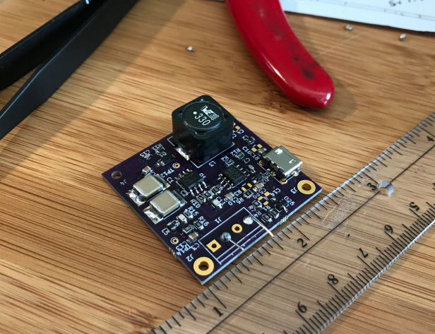
A few years ago, while managing the power management product line at work, I started an initiative with the development team to optimize new products by achieving ESE. ESE stands for Equations = Simulations = Experimentation. The idea is centered on the engineering goal of product design to verify that the systems design equations match the simulation results and ultimately the experimental results.
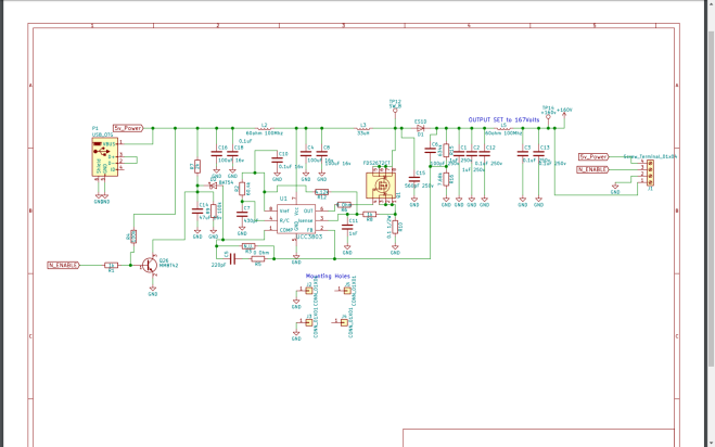
When these three items match, not only do you understand a system, but you have the best chance to optimize a better solution. I’ll have to say that in today’s mad dash to get new products out the door, achieving ESE is not always possible. But to break through the ordinary and have a chance for the extraordinary, I would say this is a requirement. Since this power supply is just a fun design for an upcoming nixie tube clock project of mine, I have the time to achieve ESE.
The updated schematic, BOM, Kicad Layout, and design files are located at Github:
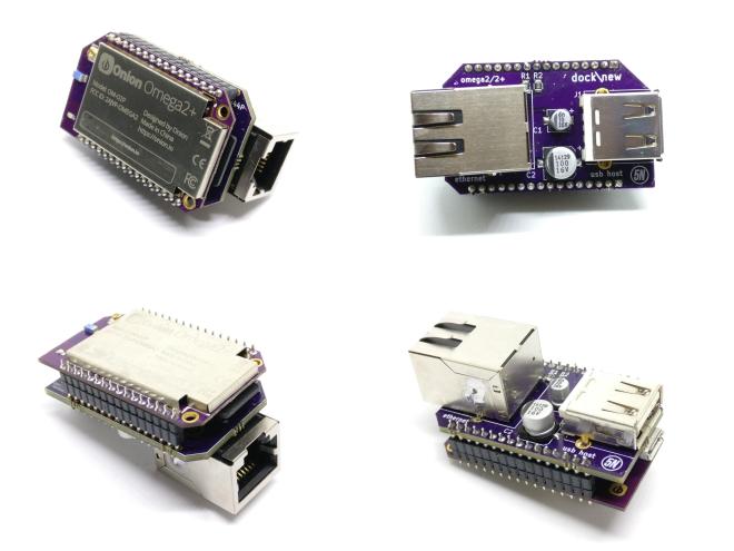
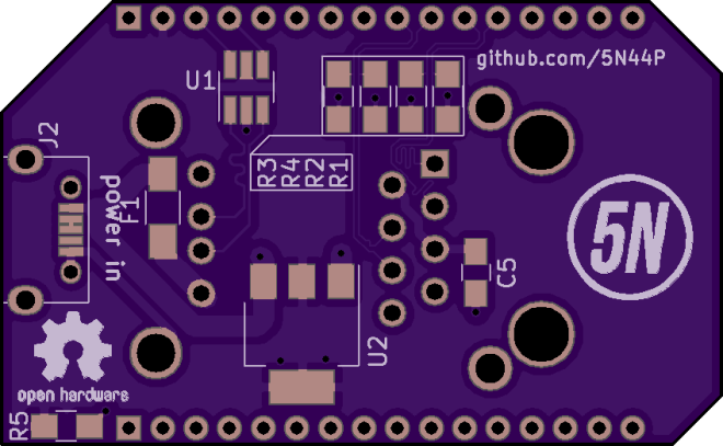
I needed the smallest dock i could do, that featured:
Ethernet
Type A USB host
Micro USB for power
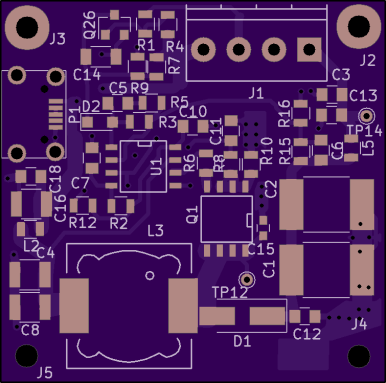
Here’s what i came up with, i called it dock\new.
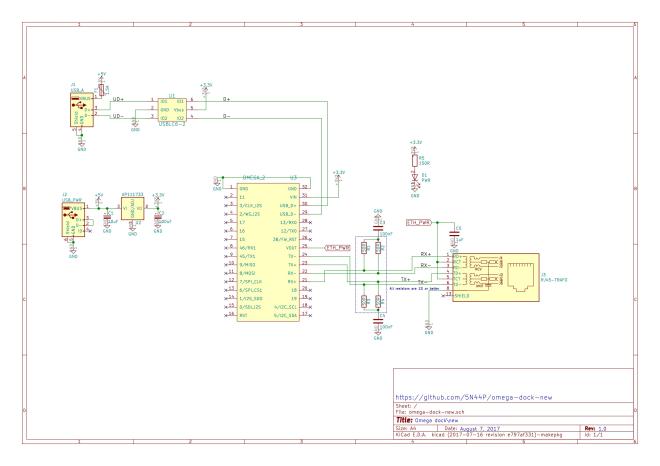
It has an onboard linear voltage regulation (i didn’t bother going with a switching one for such low power), magnetics integrated in the RJ45 connector to save space, USB host ESD protection (diode array), USB host PTC fuse.
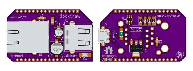
On the left side there is the RJ45 connector and nothing on the back side of the board, so that you can easily access the MicroSD card on the Omega 2+.
On the right side (the antenna side of the omega) you have the USB type A connector, facing outwards, and the microusb connector for power, facing inwards.
The project is open source (CC-BY-SA 4.0), and the KiCad schematics, board layout and the other files are available on GitHub:
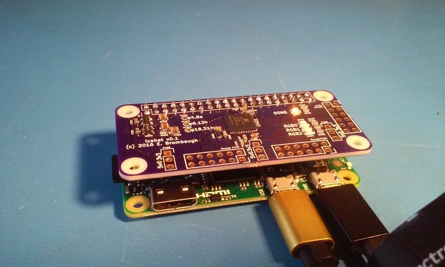
The icehat is a small (Raspberry Pi Zero-sized) board with a Lattice ice40 Ultra or Ultra Plus FPGA and three Digilent-compatible 8-bit PMOD receptacles.


")


")

")
")