Snowbot

Dan Hienzsch a holiday project to build a little Snowbot with an adjustable speed larson scanner for an eye:

snowbot_v1_prototype-2

Snowbot Ornament Project

When I started thinking of this project, I wanted to make something that included a bit of the basics and something more advanced. It had to be battery powered, and most importantly, I wanted to make sure it went against the grain of everything needing a microcontroller. Thus Snowbot was born.

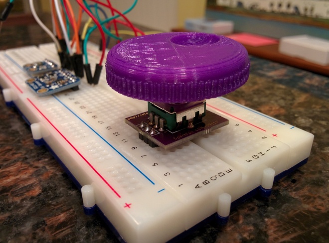
Photos from the Hackaday.io project:

RheingoldHeavy has shared the board on OSH Park:

Snowbot_2015_Rev1

snowbot_revised_silkscreen_preview

Order from OSH Park

Snowbot

LED Matrix Generator for EAGLE

Ted Yapo is designing a display for his  LED Oscilloscope Mk. II and decided to automate the process:

6979361486485114739

16×32 Display Design

I painstakingly drew the schematic for 512 LEDs in this display, then endured the drudgery of laying out the board. The whole process took about 45 seconds. Yes, I wrote a few Eagle User Language Programs (ULPs) (elapsed time after the scripts were written and debugged). The previous time I wrote one was last century to lay out a circular LED clock face. I figured it was about time I regained those skills.

8920781486146501489-1

The EAGLE ULPs are on GitHub:

led-matrix-generator

 Eagle scripts for LED matrix display generation

LED Matrix Generator for EAGLE

Rotary Encoder Breakout Board

UPDATE: Check out the new version with pull-up resistors

img_20170211_233051

I designed this simple breakout board in KiCad to make it easier to put a rotary encoder on a breadboard.   The KiCad symbol and footprint for the SparkFun rotary encoder was created by mcous on GitHub.  I used an updated version with corrected pin numbering.

img_20170211_230723

Here are the rotary encoders that I’ve verified to fit:

img_20170211_233439

The design files are available on GitHub:

Screenshot at 2017-02-14 20-58-40.png pdp7/rotary-encoder-breakout

The board is shared on OSH Park:

SparkFun Rotary Encoder Breadboard Adapter

e1911a0b6c7595c4cd7a05c4806f83bf.png

Order from OSH Park

Rotary Encoder Breakout Board

Brake Lamp Flasher for Motorcycle

Bryan Cockfield of Hackaday writes:

Brake Light Blinker Does It with Three Fives

Sometimes you use a Raspberry Pi when you really could have gotten by with an Arudino. Sometimes you use an Arduino when maybe an ATtiny45 would have been better. And sometimes, like [Bill]’s motorcycle tail light project, you use exactly the right tool for the job: a 555 timer.

boardsMore details on William F. Dudley’s project page:

Brake Lamp Flasher for Motorcycle

The 555 is a clever chip; not only will it supply the oscillator for the flashing effect, it has a reset pin that can be used to force the output to a known state (low) when (other circuitry tells it that) it’s time to stop flashing. Thus the brake light will be steady “on” after a few flashes every time the brake is applied.

brake_blinker_1_schem

The 555 is happy to run directly off the nominal 12 volt vehicle electrical system, so no voltage regulator is needed. The 555 is almost immune to electrical system noise, so no worries about your Arduino code going off into the weeds if there’s a spike from the electrical system.


Brake Lamp Flasher for Motorcycle

OnChip Open-V Arduino Compatibility

OnChip has posted a Crowd Supply update on their plans for Arduino compatibility:

arduino-open-v_jpg_project-body.jpg

Open-V Arduino Compatibility

Arduino compatibility can mean a lot of things to a lot of different people, so we’ll try to be as concrete and specific as possible. For the Open-V, Arduino development tools, and interoperating on a hardware level with existing Arduino shields.

wire-bonds-zoomed_jpg_project-body.jpg

We’ve updated our live, web-streamed demos to include an Arduino mode in addition to the assembler and C modes we already have. You might also notice the relatively new Blockly modes and a refined layout of the demo page. Go write some code and see the results live streamed!

Screenshot at 2017-02-12 20-18-49.png

OnChip Open-V Arduino Compatibility

Bristlebot with LDRs Becomes Light-Following Bristlebot

Bristlebot with LDRs Becomes Light-Following Bristlebot

Bristlebots are great because no coding is required – they’re completely analog circuits that just go! But if you wanted them to go in a specific direction, how would you do that? Facelesstech has released their design for a light-following bristlebot that uses two LDRs to drive either side of the bristlebot (so you could turn it, somewhat – see video below for demo!). It’s pretty simple and pretty clever.

img_20160815_165948 (2).jpg

The KiCad design files are available on GitHub:


Bristlebot with LDRs Becomes Light-Following Bristlebot

KiCad at FOSDEM 2017

KiCad project leader Wayne Stambaugh talked at FOSDEM 2017 about KiCad’s current status and future roadmap:

KiCad Project Status

Wayne’s slides are available on Google Drive:

Screenshot at 2017-02-14 05-47-37.png

Tomasz Wlostowski of CERN talks about the SPICE integration that was added to KiCad in 2016:

Integrated Spice Simulation


Maciej Sumiński walked through the KiCad source code:

Diving into the KiCad source code

PDF of the slides is available for download:
screenshot-at-2017-02-14-06-18-02


KiCad at FOSDEM 2017

$3 Tinusaur board on IndieGoGo

Neven Boyanov has launched a new Tinusaur campaign on IndieGoGo:

Learn, Teach and Make with the Tinusaur

Small microcontroller board that could run Arduino and help you learn, teach others and make things

uvloj5csuhcx0ri4yn5c

The Tinusaur is powered by the Atmel ATtiny85 microcontroller.

We want to bring the cost down to $3 for the basic “lite” boards
and allow more people to be able to get them.

$3 Tinusaur board on IndieGoGo