Wemos D1 Mini Breakout for an ST7735 Display

Radomir Dopieralski has created this breakout board to make it easier to slap a popular ST7735 module on top of a Wemos D1 Mini:

8571081501668647022.jpg

D1 Mini Breakout for an ST7735 Display

There is a number of options you have for display shields for the D1 Mini: there is the nice OLED shield, there is a shield with a single WS1228B neopixel, there is the #D1 Mini Matrix Shield I’m still working on. But there is no high-resolution color display you could just slap on it. This “shield” doesn’t really deserve the name, it’s just a simple breakout board that connects the ST7735 display module with the SPI pins of the D1 Mini, and adds a trim pot for brightness control.

4514121484133413329.png

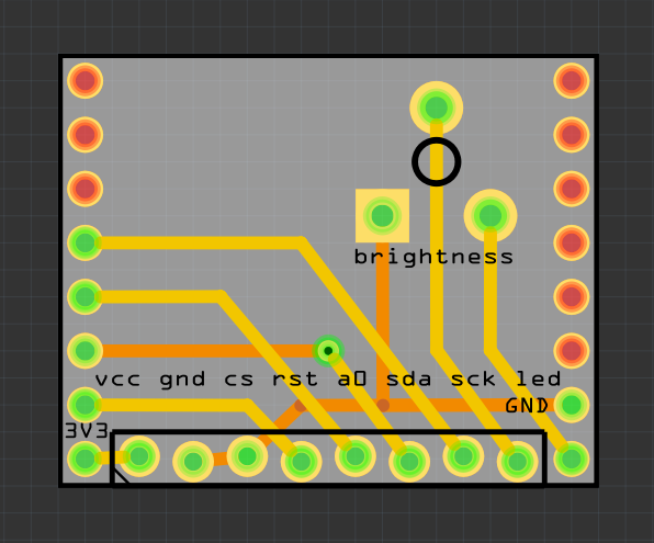
To save some pins, the CS pin is hardwired to GND, and the A0 pin is connected to MISO. That means you can’t connect other SPI devices while this is in, but that’s a rare enough case for me to care. It uses four GPIOs total, from GPIO12 to GPIO15. The backlight is connected to the 5V supply (to not strain the on-board 3V3 regulator) through a trim pot, so you can adjust brightness.

I used alternating holes for the module’s header, so that with some luck you should be able to plug in the module directly, without soldering a female pin header there — that should also save some space.

Wemos D1 Mini Breakout for an ST7735 Display

These Twenty Wheels, Wings, and Walkers Won $1000 In The Hackaday Prize

Today, we’re excited to announce the winners of the Wheels, Wings, and Walkers portion of The Hackaday Prize. We were looking for the next generation of robots, drones, machines that make machines move, and hackers who now know far too much about inverse kinematics. The results were spectacular. Hackaday is currently hosting the greatest hardware competition on…

via These Twenty Wheels, Wings, and Walkers Won $1000 In The Hackaday Prize — Hackaday

These Twenty Wheels, Wings, and Walkers Won $1000 In The Hackaday Prize

3D Scanner HAT for Raspberry Pi

From Jonathan Cohen on Tindie:
unnamed.jpg

3D Scanner HAT for Raspberry Pi

3D Scanner HAT expansion board interface for Raspberry Pi running FreeLSS on the PICLOP ATLAS FreeLSS


I wanted to make a custom interface for use with the open-source 3D Scanning software, FreeLSS. I was very impressed with the Arduino-based Ciclop scanner and the Raspberry Pi-based Atlas Scanner. Several FreeLSS users merged the two scanner platforms, creating the PiCLOP 3D Scanner. However, there were few changes to the basic PCB design used for the scanner. I wanted to integrate the hardware functionality into a Raspberry Pi HAT format, with the inclusion of extra features for expandability — and who knows, other uses !


What makes it special?

  • Conforms to the Pi Foundation specification for HATs !
  • 5V power design (only a single voltage) allowing for Pololu low-voltage stepper driver carrier.
  • Connections for up to two independent soft-PWM controlled LED light sources.
  • I2C interface for OLED displays and light intensity sensors, e.g. TSL2561 or TSL2591.
  • Serial communication breakout for console support.
  • Additional GPIO signal breakouts for other sensors and devices.
  • User-programmable EEPROM ! for auto-configuration and device overlays.
  • Standard DC power connector for up to 5V 4A power supply and connections for power switch.
  • Over-current protection by poly re-settable fuse.
3D Scanner HAT for Raspberry Pi

STM32L4 Sensor Tile

From Kris Winer on Hackaday.io:

316281486923705430.jpg

STM32L4 Sensor Tile

Small, connected device for smelling and hearing in any environment.

This is a 20 mm x 20 mm four-layer pcb tile full of interesting sensors (ICS43434 I2S Digital Microphone, MPU6500 acclerometer/gyro, BME280 pressure/temperature/humidity, and CCS811 air quality) with a Rigado BMD-350 UART BLE bridge for sending data to a smart phone all managed by a STM32L432 host MCU.

The STM32L432 is programmed using the Arduino IDE via the USB connector and serial data can be displayed on the serial monitor to verify performance and proper function, etc. But it is intended to be powered by a small 150 mAH LiPo battery for wireless sensing applications. The STM32L4 is a very low power MCU and with proper sensor and radio management it is possible to get the average power usage down to the ~100uA level, meaning a 150 mAH LiPo battery can run the device for two months on a charge.

A library for it is available on GitHub:

kriswiner/SensorTile

A collection of sketches to run the STM32L432-based (20 mm x 20 mm) sensor tile with an MPU6500 accel/gyro, ICS43434 I2S digital microphone, BME280 temperature/pressure/humidity sensor, and CCS811 air quality sensor. The sensor tile has an on-board MAX1555 LiPo battery charger, an on/off switch, and a Rigado BMD-350 nRF52 BLE module.


STM32L4 Sensor Tile

4CHord MIDI

From Sven Gregori on Hackaday.io:

5817401500854057027.jpg

the USB MIDI keyboard dedicated to play all the four chord songs, from Adele via Green Day and Red Hot Chilli Peppers to U2 and Weezer. Thanks to MIDI, you can be any instrument – and all of them at once. Yay!
 Built around an AVR ATmega328 and Objective Development’s V-USB library, 4chord MIDI acts as a regular USB MIDI instrument. It supports playback in every key and five different playback modes:
  • simple triad chord (root, third, fifth)
  • triad chord + third + fifth + third as quarter notes
  • triad chord + third + fifth + octave as quarter notes
  • root note + third + fifth + third as quarter notes
  • root note + third + fifth + octave as quarter notes

The playback tempo can be set between 60 and 240 bpm.

Here is the board in action:

The design files and source code are available on GitHub:

sgreg/4chord-midi

4CHord MIDI

Hackaday Prize Entry: USB Packet Snooping

Sometimes you run into a few problems when developing your own hardware, and to solve these problems you have to build your own tools. This is exactly how [KC Lee]’s USB Packet Snooper was created. It’s a small device that allows for capturing and analyzing Full Speed USB traffic to debug one of [KC]’s other Hackaday…

via Hackaday Prize Entry: USB Packet Snooping — Hackaday

Hackaday Prize Entry: USB Packet Snooping

SSD1306 1.3″ OLED SPI breakout board

Rene van der Meer designed this breakout board for a bare OLED display:

ssd1306-10a-disp.jpg

SSD1306 1.3″ OLED SPI breakout board

I’ve been playing with cheap OLED display breakouts for years, incorporating complete boards into my projects – an easy, but bulky solution. Now that I’ve had some practice designing circuits and PCBs, it’s time for my next challenge: soldering the display FPCs directly to my own boards.

ssd1306spi-10a-sch

I designed this board to try out a minimal circuit before integrating it into any larger projects, and to figure out the best way to solder flexible circuits to my boards. Since all of my new microcontroller-powered board designs only require 3.3 V, I haven’t added any 5 V tolerant level shifting. What’s left is a bare minimum circuit to drive a Solomon Systech SSD1306 using SPI at 3.3 V.

ssd1306-10a-back

golemparts has shared the board on OSH Park:

SSD1306 SPI Breakout v1.0 A

15d3c74ba0338db3d3a4469e58673f9b
Order from OSH Park

SSD1306 1.3″ OLED SPI breakout board

Raspberry Pi Soft Power Controller

James Lewis designed this AVR based power controller for the Raspberry Pi that can safely shutdown the Pi:

6549371493595134727

Raspberry Pi Soft Power Controller

The total circuit includes an AVR microcontroller, a near-zero current LDO, and a switching (buck) supply. My current design draws about 350nA when Vin is 9V. The AVR controls power to the Raspberry Pi. Two GPIO pins are used. One for the AVR to initiate a shutdown and one for Raspberry Pi to tell AVR after filesystem has been unmounted.
The design files and source are shared on GitHub:

baldengineer/Raspberry-Pi-Soft-Power-Controller

Raspberry Pi Soft Power Controller

Automated Pool Controller

Jerad Jacob designed this board to monitor and control a swimming pool:

pool_controller.jpg

Here-Be-Dragons/Pool-Controller

Cloud-based pump speed, solar collector controls, and temperature monitoring for your pool with SmartThings and Alexa integration

Timer Control of a Hayward Tristar VS Pump and Hayward GL-235 Solar Pool Controller

Tristar_VS_Relay_Wiring

osmosis has shared the project on OSH Park:

Pool Controller v2.2

7bab38e474b55dd8cd763149769d444f.png
Order from OSH Park

Automated Pool Controller

Game Gear HDMI with SNES Controller

From on the Hackaday log:
BhOyW7P

Game Gear HDMI with SNES Controller

With its backlit color screen and Master System compatibility, the Game Gear was years ahead of its main competition. The major downside was that it tore through alkaline batteries quickly, and for that reason the cheaper but less equipped Game Boy was still able to compete.  Since we live in the future, however, the Game Gear has received new life with many modifications that address its shortcomings, including this latest one that adds an HDMI output.

tf6Skxn
Here is a video of it in action:

Very early prototype using my GBA HDMI board to get a 1280x720p output from the Game Gear.

The custom PCB uses a Spartan6 FPGA to convert the Game Gear’s 160×144 12-bit RGB video into a 1280x720p HDMI output using a 4x integer scale. HDMI video is generated directly from the FPGA, audio is taken from the Game Gear’s headphone jack.

It has some pixel glitches, but it could be due to the wiring as it’s very sensitive to positioning. The Game Gear was bought as a “broken” unit and is in need of a cap replacement, that could also be causing issues.

Game Gear HDMI with SNES Controller