Pidgeon 1 Sub-GHz Radio

Pidgeon 1 on Crowd Supply is a sub-GHz radio with 500 mW transmission power, RS485 networking interface and a STM32F0 microcontroller:
front-and-back_jpg_project-body

Crowd Supply: Pidgeon 1

No more restrictions from high level software! Access the lowest level of digital radio transmission with this programmable sub-GHz wireless module.

Hardware Specifications:

  • Radio – CC1120 + CC1190
  • Controller – STM32F051K6
  • FTDI USB interface – FT234XD-R
  • RS485 interface – LTC2850IDD
  • Buck converter – RT8010GQW
  • SMA connector for antenna
Pidgeon 1 Sub-GHz Radio

14-bit 80MSPS ADC for SDR experiments

Eric Brombaugh designed this ADC board for RF signals:

rxadc14.jpg

RXADC_14 Pmod

This is an ADC designed for use in digitizing RF signals with up to 40MHz bandwidth and 80dB SNR. The form-factor is compatible with a dual-connector Digilent Pmod so that it can be used with commonly available FPGA development boards to build a variety Software-Defined radio functions.

Features:

  • ADC14C105 14-bit 105MSPS RXADC.
  • Onboard 3.3V Regulator (5V input)
  • Filtered Analog 3.3V Supply
  • Onboard 80MHz clock oscillator
  • Digilent-compatible 2-connector Pmod interface
  • 50-ohm SMA input – 2.5Vpp ~= 0dBfs

emeb has shared the board on OSH Park:

14-bit 80MSPS ADC for SDR experiments

831aa0bd88f188310e6a04a187a105ae
Order from OSH Park

14-bit 80MSPS ADC for SDR experiments

Star Trek Communicator Badge

Joe Crop is a creating a real life version of this famous sci-fi device:

5816181488348081070.jpg

Star Trek Communicator Badge

In the true spirit of Star Trek, this communicator badge is completely autonomous, while fitting in the form factor of an original badge

Star Trek was known for dreaming up technology that was deemed nearly impossible given the limitations of the technology for the day. Having a small badge that could send audio across vast distances seemed out of the realm of possibility during the late 1980’s. This project’s aim is to use modern technology to provide nearly all the features of visionary tech, namely:

– Tap to connect and communicate instantly
– Long range (from orbit to planet surface)
– Small form factor (of an original TNG badge)
– Fully autonomous (no cell phone or base station needed)
– No external power source (i.e. battery powered)

joecrop has shared the board on OSH Park:

Star Trek Communicator v2p1

835069b4b13a4e83663a224caebe344b

Order from OSH Park

Star Trek Communicator Badge

ESP8266 Pogo Jig Programming Board

We like the novel orientation of pogo pins that Wing Tang Wong used in this board design:

screenshot-from-2017-02-28-12-59-47

ESP8266 Pogo Jig Programming Board

Upcycles D1 Mini Wemos board to create a USB connected ESP8266 Pogo pin jig

2034481488075526204.JPG

This is a board designed to take a WeMos D1 Mini board(with the ESP module removed) and use it as a USB interface with built-in reset/flash functionality for bare ESP8266 modules similar to the ESP-12 units.

The design files are available on GitHub:

github ESP8266 Programming D1 Mini Pogo Jig V1

ESP8266 Pogo Jig Programming Board

DTV Tuner Breakout for SDR

Eric Brombaugh designed this breakout board for the Rafael Microelectronics R820T2 Advanced Digital TV Silicon Tuner chip:

r820t2_breakout_assembled

R820T2 Breakout

This is the same chip used in most all of the RTL-SDR dongles, as well as the Airspy and numerous other radios. The chip is a versatile front-end with reasonable sensitivity and wide tuning range.

screenshot-at-2017-02-17-13-54-36

The design presented here is almost an exact implementation of the Mfg’s suggested demo design from the datasheet, implemented on the OSHpark 4-layer PCB process and provides a simple 4-pin interface with power, ground and I2C bus for controlling the tuner. A broad-band RF input and 10MHz IF output are provided on SMA connectors.

The breakout PCB design and STM32F0 firmware for the Rafael R820T2 tuner chip are shared on GitHub:

screenshot-at-2017-02-14-20-58-40 emeb/r820t2


emeb has shared project on OSH Park:

r820t2_breakout v0.1

cd102a38f8c39fe1ff2d6fe4cfe90e12.png
Order from OSH Park

DTV Tuner Breakout for SDR

Onion Omega2 Breakout

tumblr_ojbxowFrFv1tja38uo3_1280.jpg

Onion Omega2 Breakout

My Omega2 Onion shield, using a AMS1117 for 3.3V and CH340G for USB to serial. Kind of ugly soldering here as I didn’t have a tip for the syringe to dispense solder paste, so I just smeared it all over and hoped it reflowed well. It kind of did, but I had a solder blob short on pin 14 +15 on the CH340G, so I just lifted those two legs off the board. I was so eager to get this board tested that I forgot to check that I had these 2mm pin headers. I had just enough to get this thing tested. Time to order more 🙂

tumblr_ojbxowfrfv1tja38uo2_1280

Jensa has shared the board on OSH Park:

Onion Omega2 Breakout

fe1620694e5f9a5bb93bbfb970d31ff0
Order from OSH Park

Simple breakout board using the dirt cheap IC’s CH340G ($0.30/each on ebay) for Serial and a AMS1117-3.3 ($0.025/each) for power. Breaks out all pins from 2mm to 2.54mm headers. Plugs nicely into two small breadboards for prototyping.

Onion Omega2 Breakout

PCB Design Guidelines to Minimize RF Transmissions

screenshot-at-2017-01-27-10-24-11

 writes on Hackaday:

PCB Design Guidelines to Minimize RF Transmissions

There are certain design guidelines for PCBs that don’t make a lot of sense, and practices that seem excessive and unnecessary. Often these are motivated by the black magic that is RF transmission. This is either an unfortunate and unintended consequence of electronic circuits, or a magical and useful feature of them, and a lot of design time goes into reducing or removing these effects or tuning them.

You’re wondering how important this is for your projects and whether you should worry about unintentional radiated emissions [..]

Another good guide is Michael Ossmann’s simple RF design rules:

five_rules.png


PCB Design Guidelines to Minimize RF Transmissions

iceRadio SDR

rx.png

From the Hackaday blog:

Ice, Ice, Radio Uses FPGA

Building a software defined radio (SDR) involves many trades offs. But one of the most fundamental is should you use an FPGA or a CPU to do the processing. Of course, if you are piping data to a PC, the answer is probably a CPU. But if you are doing the whole system, it is a vexing choice.

iceradio

The FPGA can handle lots of data all at one time but is somewhat more difficult to develop and modify. CPUs using software are flexible–especially for coding user interfaces, networking connections, and the like) but don’t always have enough horsepower to cope with signal processing tasks (and, yes, it depends on the CPU).

Screenshot from 2017-01-23 18-49-55.png

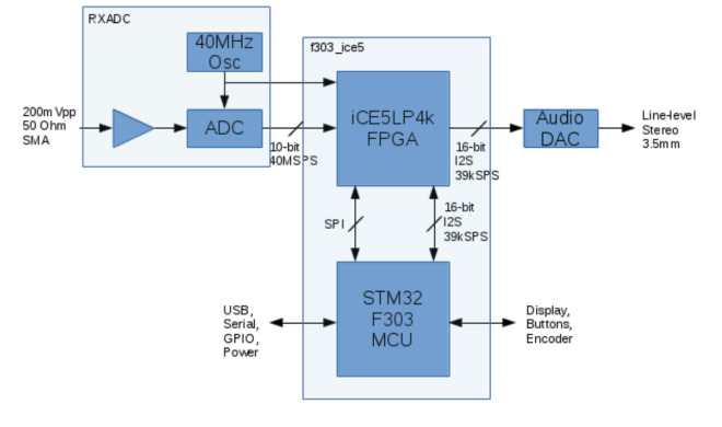
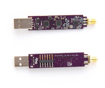
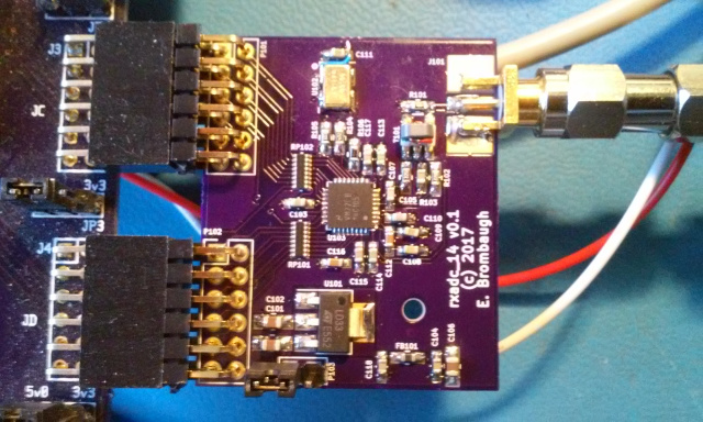
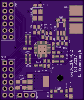
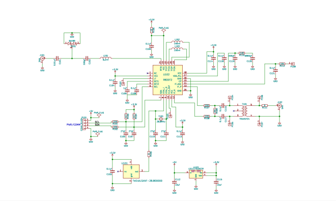
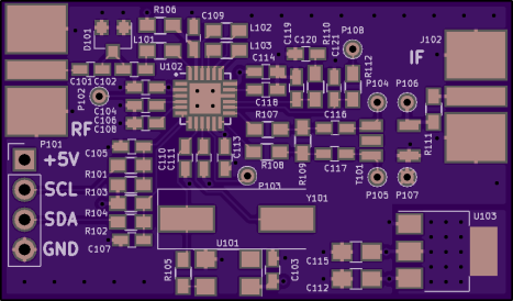
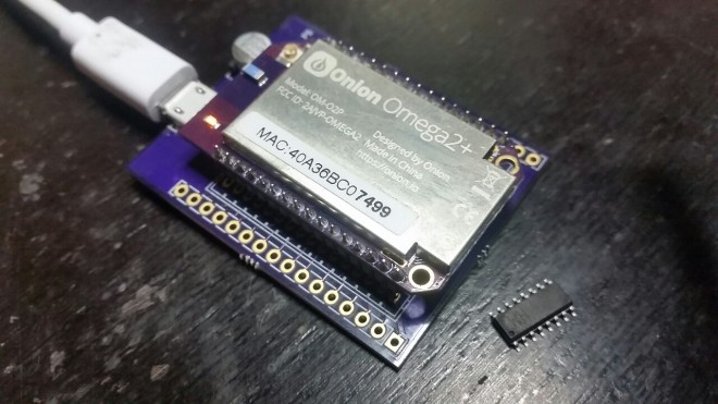
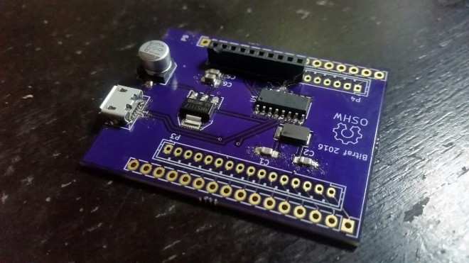
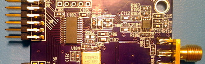
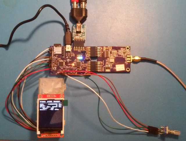
[Eric Brombaugh] sidestepped that trade off. He used a board with both an ARM processor and an ICE FPGA at the heart of his SDR design. He uses three custom boards: one is the CPU/FPGA board, another is a 10-bit converter that can sample at 40 MSPS (sufficient to decode to 20 MHz), and an I2S DAC to produce audio. Each board has its own page linked from the main project.Z

k.png

The iceRadio project page has additional details:

Design files and source code are available on GitHub:

images11emeb/iceRadio


iceRadio SDR

Drinkro the Synchro Bartender

Synchro Labs created this project to demonstrate the use of the Synchro mobile app platform with custom hardware:

DrinkroCallouts.jpg

Drinkro Cocktail Robot

based on a Raspberry Pi 3 Model B and a custom-designed hardware board used to control four DC liquid peristaltic pump motors using two L293D dual H-bridge ICs

Hardware design files are available on GitHub:

images11SynchroLabs/DrinkroHardware


Video of Drinkro in action:

https://www.youtube.com/watch?v=6KpcA1cZvbw

Drinkro the Synchro Bartender